Complete level and ramp program, Program tolerance function - ptol, Programs with few segments – NOVUS Controller N480D User Manual
Page 4: Successive repetitions of a program, Determination of pid parameters, Alarms functions
N480D Controller
NOVUS AUTOMATION
4/6
disabled (run = no) and all outputs are turned off. With value 0 in t SP
the control continues indefinitely without time limit.
As alarm can be associated at the end of the level. The End.t Alarm
Function determines that an alarm is activated at the end of the level.
Valid only with t sp ≠ 0.
Fig. 4 - Level Ramp Function
Upon returning from a power failure, the controller automatically restarts
the execution of the Ramp to Level function. If the PV value is smaller
than the SP value, the Ramp restarts at this point until it reaches SP. If
the temperature is equal to SP, Level execution is restarted.
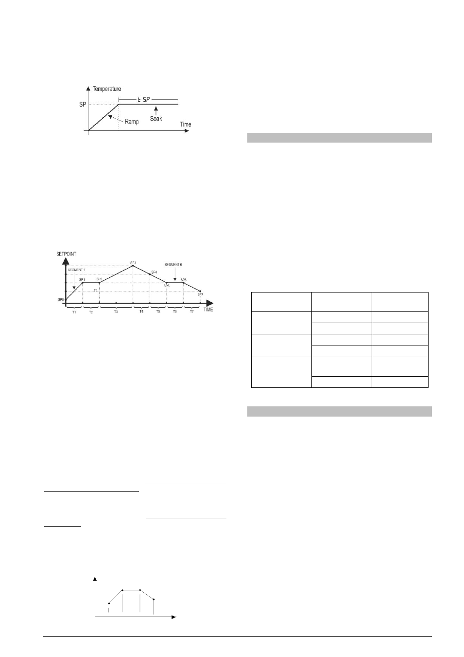
COMPLETE LEVEL AND RAMP PROGRAM
Available when the Pr option is selected in the Pr.Ty parameter.
The controller allows to elaborate one temperature ramp and level
program. This program is created from the SP value definition and time
intervals, defining up to nine (9) program segments. The figure below
shows a program model with 9 segments:
Fig. 04 - Example of a ramp and level program
The program created is permanently stored in the controller’s memory.
It can be modified freely, executed when necessary and repeated as
often as necessary.
In order to execute a program:
1- Turn off outputs (rvn= NO);
2- Enable execution of parameter E.Pr= yes;
3- Trigger start turning on outputs: (rvn= yes).
Once a program is initiated, the controller starts to automatically
generate the SP values defined for each program segment. SP
adjustment in the indication screen remains blocked.
PROGRAM TOLERANCE FUNCTION - PTOL
The “PtoL” program tolerance program defines the maximum error
limit between the PV and SP values during program execution. If this
limit is exceeded, the timing of the segment (Pt1…Pt9) is interrupted
until the error is within the established tolerance. With a value > 0, the
user indicates in the program that priority must be given to PV
regarding the determined time values.
If zero tolerance (Ptol = 0) is programmed, the controller executes
the program defined without considering eventual errors between PV
and SP. Thus, the user defines that the priority be given to the program
execution time.
PROGRAMS WITH FEW SEGMENTS
In order to execute a program with a smaller number of segments, just
program 0 (zero) for the time interval that follows the last segment of
the desired program.
SP
TIME
T1
T2
T3
PSP0
PSP1
PSP2
PSP3
T4=0
Fig. 05 - Example of a program with only 3 segments
SUCCESSIVE REPETITIONS OF A PROGRAM
The elaborated program can be repeated several times, always
restarting immediately after each execution.
The rPt.p (rePeat Program) parameter, in the Program cycle,
configures the number of times the program must be REPEATED. It
determines the number of executions beyond the initial execution.
With zero (0), the program is executed only one time. It will not be
repeated.
Important: After the last execution of the program, all controller outputs
are turned off and the RUN parameter changes to OFF.
DETERMINATION OF PID PARAMETERS
During the automatic tuning the process is controlled in ON / OFF
mode in the programmed SP - the Ramp to Level function is disabled.
The automatic tuning may take many minutes to the concluded,
particularly in slow processes. Some recommendations for the
automatic tuning process are:
• Program SP to a value close to the point at which the process
will operate after tuning.
• Enable automatic tuning on the “Atvn” screen by selecting 1.
• Program the value 1 on the “rvn” screen.
The “TUNE” indicator on the display stays lit until the completion of the
automatic tuning process.
During the execution of automatic tuning, large oscillations can be
induced in the process around the set point. Check if the process
supports these oscillations.
If the automatic tuning does not result in a satisfactory control, refer to
Table 3 for guidelines on how to correct the behavior of the process.
PARAMETER
VERIFIED
PROBLEM
SOLUTION
Proportional Band
Slow answer
Decrease
Great oscillation
Increase
Rate of Integration
Slow answer
Increase
Great oscillation
Decrease
Derivative Time
Slow answer or
instability
Decrease
Great oscillation
Increase
Table 3 - Guidance for manual adjustment of the PID parameters
ALARMS FUNCTIONS
The minimum and maximum alarms are used to signalize extreme
temperature values. These extreme values are defined on the “A1SP”
and “A2SP” screens.
Differential alarms are used to signalize deviations between temperature
and set point control (SP). Values defined by user on the “A1SP” and
“A2SP” screens represent the values of these deviations.
Initial blocking prevents alarm activation when the controller is turned
on until the temperature reaches the SP value for the first time.
The error alarm in the sensor allows to signalize errors in the sensor.
The Level End Function (End.t) determines that the alarm be activated
the end of the level.
With Event Alarm, an alarm is activated during execution of a certain
program segment.
Table 3 illustrates the operation of each alarm function, using alarm 1
as an example, and presents its identification code on the “A1Fv” e
“A2Fv” screens.
Using the Alarm 1 as example.