4 logchart ii software, 1 installing logchart ii, 2 running logchart ii – NOVUS TagTemp-USB User Manual
Page 2: 3 configuring the equipment
TagTemp-USB
NOVUS AUTOMATION
2/5
4 LOGCHART II SOFTWARE
4.1 INSTALLING LOGCHART II
The LogChart II, application is used to configure the parameters for
data transfer. To install the LogChart II, run the file LC_II_Setup.exe
available on our web site.
4.2 RUNNING LOGCHART II
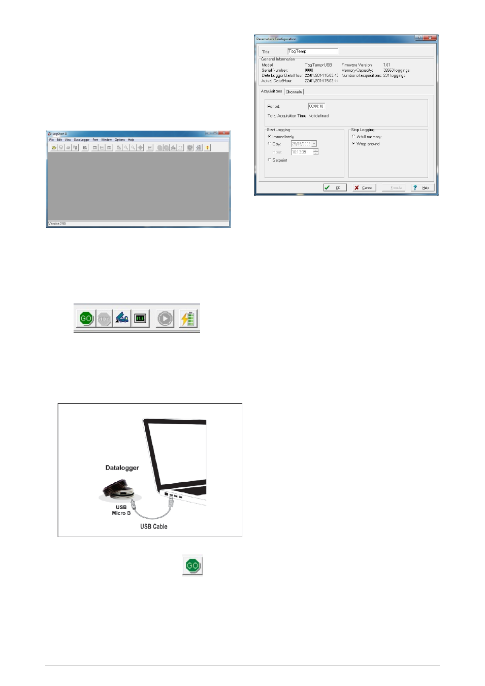
When you open LogChart II the main window is displayed.
Fig. 02 – LogChart II main window
Next, select the serial port that the communication interface will use
in the “Port” menu.
Check which serial is available. Usually COM2 is free, once the
mouse uses COM1. The chosen port will be chosen by default next
times the LogChart II is initiated. When a valid port is selected, the
icons below are displayed.
Fig. 03 – Icons enabled when the communication port selected is a valid port
4.3 CONFIGURING THE EQUIPMENT
For device configuration is necessary that the communication
interface is connected to the computer, using the selected port
described in the previous section. See figure below.
Fig. 04 – Communication via USB cable
After the serial port is selected, click on the button:
The Parameters Configuration screen is displayed. In this screen
the user can define the equipment operation mode and also obtains
general information about the device.
Fig. 05 – Configuration window
Fields are:
1- Title: In this field, the user identifies the equipment by assigning it
a name.
2- General information: Area with information about the equipment,
such as Model, Serial Number, equipment Date/Time, PC Date/Time,
firmware version, memory capacity and number of acquisitions
stored in memory.
In this field, time is constantly updated while the communication
between equipment and computer is taking place.
3- Readings: Presents a series of parameters that define the
acquisition process.
Interval: Defines the interval between readings: The minimum
interval is (5) seconds and maximum is (18) hours.
Note: When the type of value logged is minimum, maximum or
average values, the minimum interval is 50 seconds.
Estimated time: In this parameter, the equipment informs the
user how long it will take to occupy the full memory, in the
conditions set up during configuration.
Start of Readings: Readings can be started in one of three
different modes:
• Immediately: start as soon as set up is ready and sent
(OK) to the equipment.
• Date: readings start at predefined date and time.
• Setpoint: acquisitions start when a temperature setpoint
is reached. In this option, the setpoint value is defined in
the Channels field, where the Alarm parameter is
replaced by setpoint.
Stop loggings: Options for the end of readings are:
• Full Memory: readings can be stored up to the full
memory capacity is reached.
• Don’t stop (Wrap around): readings are continuous,
replacing old records with new ones as the number of
readings overpass the memory capacity.
4- Channels: Displays other parameters related to temperature
measurement:
Unit: Defines the unit of the value measured: ºC or ºF for
channel 1 (temperature).
Value: It defines how the value measured will be registered.
Options are:
• Instantaneous: The value logged will be exactly the value
measured at each interval defined. Measurement is taken
at the end of the defined interval. The minimum interval
between measurements is 5 seconds.