Customized linearization, Retransmission, Alarms – NOVUS N1500FT Indicator User Manual
Page 2: Alarm functions, Alarm timer, Alarm hysteresis, Initial alarm block, Special functions, Maximum and minimum
N1500FT Flow Indicator
NOVUS AUTOMATION
2/9
CUSTOMIZED LINEARIZATION
When the flow rate is read through a 4-20 mA input, it is possible to
apply a customized linearization composed of 30 input points and 30
output points. Whenever the reading falls between two input points, it
will be normalized to the range defined by the respective points in the
output range.
The input range considered as an input to the linearization table is
the range defined by the user in the InLL and InKL parameters (it is
not the current in mA). In case user wants to enter the values directly
in mA to convert to the desired viewing unit, parameter 1n LL must
be set as 4 (mA) and parameter 1n xl
as 20 (mA), using as many
decimal places as needed to the desired precision. It will be possible
then to enter values between 4-20 (mA) as input points for the
customized linearization.
The search for framing the value read is done while the list of input
points is incrementally declared. The search is terminated if the next
point in the list is lower than the current one. If the input value is
lower than the first value in the list of input points, linearization will
return the first output value. Similarly, if the input value is greater
than the highest value in the list of input points, linearization will
return the highest value in the output list.
IMPORTANT: At least two pairs of input-output points are required
for adequate customized linearization.
RETRANSMISSION
Flow rate retransmission can be done via 4-20 mA output and pulse
output.
The 4-20 mA output may be used regardless of the type of flow input.
To use it, just set the retransmission range to RTLL and RTKL,
associating the flow rates to 4-20 mA.
In the case of retransmission via pulse output, one must choose
between volumetric pulse output and frequency pulse output. The
former may be used regardless of the type of input, while the latter is
available only for pulse inputs.
In the volumetric mode, a pulse of configurable length is generated
every time the totalizer accumulates a preset volume. For example,
for a period of 1 second and volume of 10 liters, a 1-second pulse will
be generated for every 10 liters totalized. The counting to the output
pulse will be reset every time the user resets the totalizer or
whenever a feeding process is finished.
Note: In case the feeding process is running and the totalizer is reset
by the user, the process will remain running normally, but the output
pulse will not be synchronized with this process anymore, which can
lead to a missing pulse informed at the end of the feeding process.
As it is always reset at the end of the process, output pulse counter
will synchronize again for a new feeding process.
In the frequency mode, the pulse output will divide the input
frequency by a programmable constant whose value is equal to or
higher than 2.
IMPORTANT: Maximum output frequency has hardware limitation.
See Specifications. Check the “Specifications”.
ALARMS
The indicator’s basic version has 2 alarm outputs, with the option of
up to 4 alarms. Whenever an alarm is on, a corresponding light
signal will be displayed on the front panel.
ALARM FUNCTIONS
The alarms can be programmed to operate with four different
functions, described below. They may also be turned off.
Alarms use only the instantaneous flow rate reading. Totalization
readings cannot be used as input for alarms. The auxiliary 4-20 mA
input (when it is not being used for flow rate measurement) may be
used only as input for the open sensor alarm.
• Open Sensor – I.error
The open sensor alarm operates whenever the input sensor is badly
connected or broken. Valid only for 4-20 mA inputs.
• Minimum Value – Lo
It sets off when the reading is below the value determined by the
alarm Setpoint.
• Maximum Value – Ki
It sets off when the reading is above the value determined by the
alarm Setpoint.
• Feeder Function – FEEDER
It activates the output relay when it is started by pressing
or
via the auxiliary digital input (according to setup) and deactivates
when the reading reaches the value determined by the alarm setpoint
or when the
key or digital input is pressed/closed again,
putting the process on hold. In case of pressing the
key or
digital input more than 3 seconds, process is reset and stays waiting
to be started.
Further details in the “
” section.
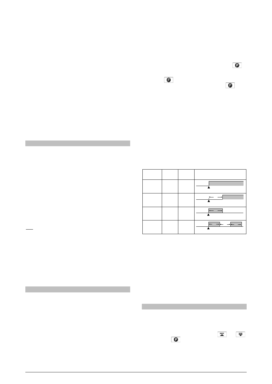
ALARM TIMER
The indicator allows setting up an Alarm Timer, where users can set
the alarm to go off with a delay, to go off in only one pulse or to go off
in sequential pulses.
Figures in Table 1 show these functions. There, times T1 and T2
may vary from 0 to 32000 seconds and are defined while
programming the indicator. For regular (no timers) operation of
alarms, simply set T1 and T2 to 0 (zero).
He alarm light signals will be displayed whenever there is alarm
condition, regardless of the current status of the output relay, which
may be temporarily out of power because of the timer function.
ADVANCED
FUNCTION
T1
T2
ACTION
Regular
Operation
0
0
Delay
0
1 to 32000
Pulse
1 to 32000
0
Oscillator 1 to 32000 1 to 32000
Table 1 - Alarm timer functions
ALARM HYSTERESIS
Hysteresis defines the difference between the value measured when
the alarm is triggered and the value at which it is deactivated.
INITIAL ALARM BLOCK
The initial block option prevents the alarm from going off in case there
is alarm condition at the time the indicator is being energized. The
alarm may be triggered only after a non-alarm condition is followed by
an alarm condition. This function is not valid for alarms programmed as
Open Sensor.
SPECIAL FUNCTIONS
MAXIMUM AND MINIMUM
The flow indicator continuously records the minimum and maximum
values of instantaneous flow rate. These values can be viewed on
the first screen of the main cycle by pushing
and
,
respectively. The
key can be set to zero maximum and
minimum values.
Alarm Event
Alarm
Output
Alarm Event
Alarm
Output
T2
Alarm Event
Alarm
Output
T1
Alarm Event
Alarm
Output
T1
T2
T1