Optical rotation, Terminal block, Maintenance and cleaning optional photocontrol – American Electric Lighting ASA User Manual
Page 2
American Electric Lighting a division of Acuity Lighting Group, Inc. Conyers, GA
DRAWING NO. A67853 REV -
(BACK)
©2005 ACUITY LIGHTING GROUP, INC.
PART NUMBER 057-70-67853
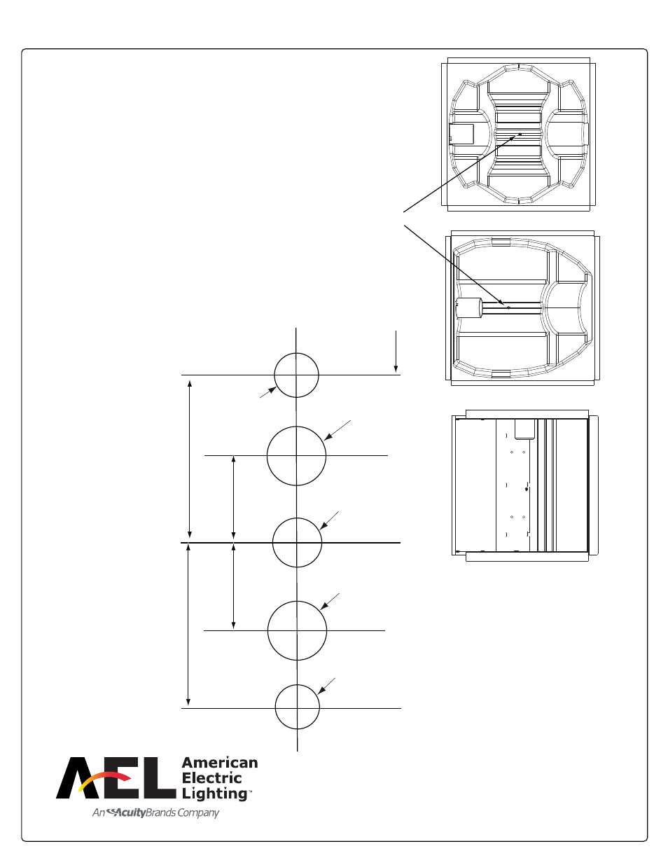
Optical Rotation
R4
R2 / R3
R5
S
T
R
E
E
T
S
I
D
E
REFLECTOR SCREW
S
T
R
E
E
T
S
I
D
E
Open door assembly. Loosen the reflector screw and remove.
Rotate the optical assembly to desired output position.
Note in R2 / R3 and R5 distributions which is streetside.
Insert the reflector assembly back into the housing and
tighten reflector screw.
Terminal Block
Check the voltage values of the ballast leads attached to one
side of the Terminal Block. Place the corresponding incoming
line voltage leads, being sure to observe proper polarity and
voltage. Secure by tightening the screws.
Maintenance and Cleaning
Optional Photocontrol
The optical assembly should be cleaned with a mild
detergent and rinsed well with clean water to maintain
the efficiency of the luminaire. See the instruction under
Assembly, Mounting and Wiring to open the bezel.
Lift and rotate the receptacle to the North. Insert
the Photocontrol and twist it clockwise until it locks
into position.
NON ROTATABLE
2 1/8"
1 1/8"
1 1/8"
2 1/8 "
2 3/4" Min. Recommended
from top of pole
See Note
5/8" Dia. Wire Entry
See Note
9/16" Dia.
9/16" Dia.
Note: Important - For Wall or Wood Pole
Mounting Only. Hole Size is
Determined by Fasteners Supplied
(By Others). Minimum Fastener Size
is 1/2 " Dia. Maximum 5/8" Dia.