Caution – American Electric Lighting AVL new User Manual
Page 2
American Electric Lighting a division of Acuity Lighting Group, Inc. Conyers, GA
DRAWING NO. A66193 REV A
(BACK)
©2004 ACUITY LIGHTING GROUP, INC.
PART NUMBER 057-71-66193
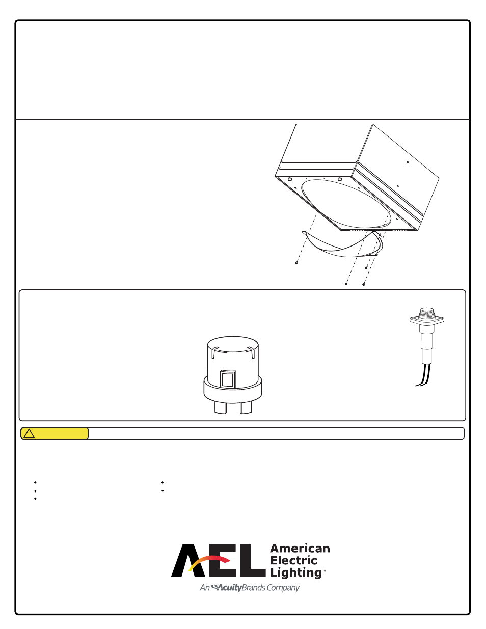
FACTORY INSTALLED OPTIONS
FACTORY INSTALLED OPTIONS
FACTORY INSTALLED OPTIONS
FACTORY INSTALLED OPTIONS
FACTORY INSTALLED OPTIONS
NEMA TWIST LOCK RECEPTACLES AND PHOTOCONTROL
NEMA TWIST LOCK RECEPTACLES AND PHOTOCONTROL
NEMA TWIST LOCK RECEPTACLES AND PHOTOCONTROL
NEMA TWIST LOCK RECEPTACLES AND PHOTOCONTROL
NEMA TWIST LOCK RECEPTACLES AND PHOTOCONTROL
Photocell receptacle: PR
Photocell receptacle: PR
Photocell receptacle: PR
Photocell receptacle: PR
Photocell receptacle: PR
The photocell receptacle is factory installed, and be ordered with
MUST
MUST
MUST
MUST
MUST
the fixture as it is wired to correspond with the voltage of the fixture.
Photocontrols
Photocontrols:
Photocontrols:
Photocontrols:
Photocontrols: The photocontrol is shipped separately
and must be field installed.
Important:
Important:
Important:
Important:
Important: The voltage of the photocontrol must
be the same as the fixture voltage.
SINGLE/DOUBLE FUSING - complete with fuses
SINGLE/DOUBLE FUSING - complete with fuses
SINGLE/DOUBLE FUSING - complete with fuses
SINGLE/DOUBLE FUSING - complete with fuses
SINGLE/DOUBLE FUSING - complete with fuses
S F
S F
S F
S F
S F - Single Fuse is internally accessible for use
with 120, 277, or 347 volt fixtures
DF
DF
DF
DF
DF - Double Fuse is internally accessible for use
with 208, 220, 240, or 480 volt fixtures.
TROUBLESHOOTING
TROUBLESHOOTING
TROUBLESHOOTING
TROUBLESHOOTING
TROUBLESHOOTING
If this fixture fails to operate properly, check to make sure:
The correct lamp is properly installed.
The fixture is grounded correctly.
The fixture is wired correctly.
The line voltage at the fixture is correct.
The lamp is not faulty.
If all these variables have been checked and the fixture still does not operate as specified, contact your local American Electric Lighting distributor or agent.
Observe lamp manufacturer’s recommendations and restrictions on lamp operations, particularly ballast type, burning position, etc.
MAINTENANCE:
MAINTENANCE:
MAINTENANCE:
MAINTENANCE:
MAINTENANCE: Your fixture is designed for years of trouble-free operation. For optimum performance, periodically clean reflector and lens with a soft, damp cloth.
IMPORTANT: DO NOT
DO NOT
DO NOT
DO NOT
DO NOT use abrasive materials, glass cleaner or other solvents on lens or paint. Use only mild, soapy water.
Glass Lens Change
Glass Lens Change
Glass Lens Change
Glass Lens Change
Glass Lens Change
Tools Needed: 1/2" wrench or socket
(For convenience, the lens is interchangable from a flat full cutoff lens to a contoured drop lens or drop lens to flat lens)
1. Open the doorframe assembly, loosen the (4) lens clips securing nuts using a 1/2" wrench or socketsand remove them from the studs being careful to keep the lens
from falling or being damaged.
2. Take the existing lens gasket and place on new lens, place lens in doorframe assembly and re-apply the (4) lens securing clips and their (4) nuts securing well.
(Do not secure to the point of bending the clips)
Note:
Note:
Note:
Note:
Note: The optical reflectors are SPECIFICALLY designed for their respective lens option. We can not accept responsibility for photometric performance when
The optical reflectors are SPECIFICALLY designed for their respective lens option. We can not accept responsibility for photometric performance when
The optical reflectors are SPECIFICALLY designed for their respective lens option. We can not accept responsibility for photometric performance when
The optical reflectors are SPECIFICALLY designed for their respective lens option. We can not accept responsibility for photometric performance when
The optical reflectors are SPECIFICALLY designed for their respective lens option. We can not accept responsibility for photometric performance when
these are not matched.
these are not matched.
these are not matched.
these are not matched.
these are not matched.
EHS (External Houseside Shield) Option
Tools Required: Drill, 5/32" drill bit, slotted screwdriver or 5/16" nut driver
The EHS is unique and aesthetically pleasing design that can be rotated to any
desired side needed to help eliminate unwanted spill light.
1.
1.
1.
1.
1. Choose the side needed to apply the shield. Align the shield in this position
Choose the side needed to apply the shield. Align the shield in this position
Choose the side needed to apply the shield. Align the shield in this position
Choose the side needed to apply the shield. Align the shield in this position
Choose the side needed to apply the shield. Align the shield in this position
and choose the four indicator dimples that need to be drilled out, mark or
and choose the four indicator dimples that need to be drilled out, mark or
and choose the four indicator dimples that need to be drilled out, mark or
and choose the four indicator dimples that need to be drilled out, mark or
and choose the four indicator dimples that need to be drilled out, mark or
remember
remember
remember
remember
remember which dimples will be drilled.
which dimples will be drilled.
which dimples will be drilled.
which dimples will be drilled.
which dimples will be drilled.
2.
2.
2.
2.
2. Setting shield aside, open doorframe in order to keep drill from penetrating
Setting shield aside, open doorframe in order to keep drill from penetrating
Setting shield aside, open doorframe in order to keep drill from penetrating
Setting shield aside, open doorframe in order to keep drill from penetrating
Setting shield aside, open doorframe in order to keep drill from penetrating
reflector. Drill the indicator dimples chosen with 5/32" drill bit, being careful not
reflector. Drill the indicator dimples chosen with 5/32" drill bit, being careful not
reflector. Drill the indicator dimples chosen with 5/32" drill bit, being careful not
reflector. Drill the indicator dimples chosen with 5/32" drill bit, being careful not
reflector. Drill the indicator dimples chosen with 5/32" drill bit, being careful not
to penetrate the lens gasket by keeping drill perpendicular to the doorframe.
to penetrate the lens gasket by keeping drill perpendicular to the doorframe.
to penetrate the lens gasket by keeping drill perpendicular to the doorframe.
to penetrate the lens gasket by keeping drill perpendicular to the doorframe.
to penetrate the lens gasket by keeping drill perpendicular to the doorframe.
3.
3.
3.
3.
3. Close the doorframe and secure it. Align shield with chosen drilled holes,
Close the doorframe and secure it. Align shield with chosen drilled holes,
Close the doorframe and secure it. Align shield with chosen drilled holes,
Close the doorframe and secure it. Align shield with chosen drilled holes,
Close the doorframe and secure it. Align shield with chosen drilled holes,
install the 4 screws provided with phillips type screwdrive.
install the 4 screws provided with phillips type screwdrive.
install the 4 screws provided with phillips type screwdrive.
install the 4 screws provided with phillips type screwdrive.
install the 4 screws provided with phillips type screwdrive.
CAUTION
!