Maintenance - all year – COOK HMD EN User Manual
Page 6
6
left to right. Use a screw driver on top of modular
gas valve. While monitoring the unit’s temperature
rise, set the maximum firing rate by adjusting the
regulator until the designed temperature rise is
achieved. After setting the maximum firing rate,
reconnect the wire to the amplifier. Do not set the
burner maximum firing rate based on gas pressure.
It should be set based on the unit’s designed
temperature rise shown on the label. Setting the
maximum firing rate during mild weather conditions
may cause the high limit to trip out during extreme
conditions requiring manual resetting. Gas trains
are equipped with a combined regulator valve.
Clockwise rotation increases the temperature
rise; counterclockwise rotation decreases the
temperature rise. The minimum setting for the
maximum firing rate may be higher than required.
This is acceptable, the burner will modulate as
needed. To convert from Natural Gas to LP or vice
versa follow the instructions associated with the
high fire gas valve.
5. Set the operating temperature.
Maintenance - All year
V-Belt Drives
NOTICE! Do not pry belts on or off
the sheave. Loosen belt tension
until belts can be removed by
simply lifting the belts off the
sheaves. When replacing
V-belts on multiple groove
drives, all belts should
be changed to provide
uniform drive loading.
Do not install new belts
on worn sheaves. If the
sheaves have grooves
worn in them, they must be replaced before new
belts are installed.
method downstream of the blower. Changing the air
volume can significantly increase the motor’s amps.
If the air volume is changed, the motor’s amps must
be checked to prevent overloading the motor. To
ensure accuracy, the dampers are to be open when
measuring the air volume.
9. Adjust the settings on the optional components.
See the Control Center Layout in the Reference
section for location of optional components.
• Heating Inlet Air Sensor
Typical setting: 60-70ºF
• Building Freeze Protection
Typical setting: 45ºF
• Dirty Filter Gauge
Typical setting: Settings vary greatly for each unit.
Gas
1. Check the supply gas pressure and compare it with
the unit’s nameplate pressure requirements. Adjust
the supply regulator as needed until the supply gas
pressure is within the specified range (see below).
The nameplate is located on the outside of the unit
on the control panel side.
2. Check the settings on the optional high and low
gas pressure switches. The high pressure setting is
typically 8 inches wc (2 kPa) and the low pressure
is setting is typically 3 inches wc (0.7 kPa). The
switches are set at the factory and should not need
adjustment. Adjust the setting only if needed. The
purpose of the high and low gas pressure switches
is to automatically shut down the burner if the inlet
gas pressure is too low for the burner to safely
light, or if the manifold pressure is too high for the
burner to operate properly. Proper air velocity over
the burner is critical on direct fired gas units. If the
air velocity is not within the unit specifications, the
unit will not operate efficiently, may have sporadic
shutdowns, and may produce excessive carbon
monoxide (CO) or other gases.
3. With all access panels in place, the fan running
and discharging 70ºF (21ºC) air, connect a U-Tube
manometer to the outer sensing probes and
measure the static pressure across the burner.
The proper static pressure should be (check CFM /
Static Pressure chart on page 8). If needed, evenly
adjust the baffles, keeping the burner centered in
the opening until the required pressure is obtained.
The pressure drop was set at the factory and may
not need adjustment. When required pressure is
obtained, be sure to reconnect the outer sensing
probes. This process may need to be repeated until
the proper pressure is achieved. This adjustment
will change the air quantity delivered by the unit
and therefore the air quantity delivered should be
rechecked. Refer to the Blower Start-Up section.
• To increase static pressure decrease the opening.
• To decrease static pressure increase the opening.
4. Monitor the unit’s actual temperature rise by placing
a thermocouple in the unit’s inlet and a second in
the discharge, three duct diameters downstream
of the burner. Send the unit to maximum flame
by changing the rotation of the motor pack from
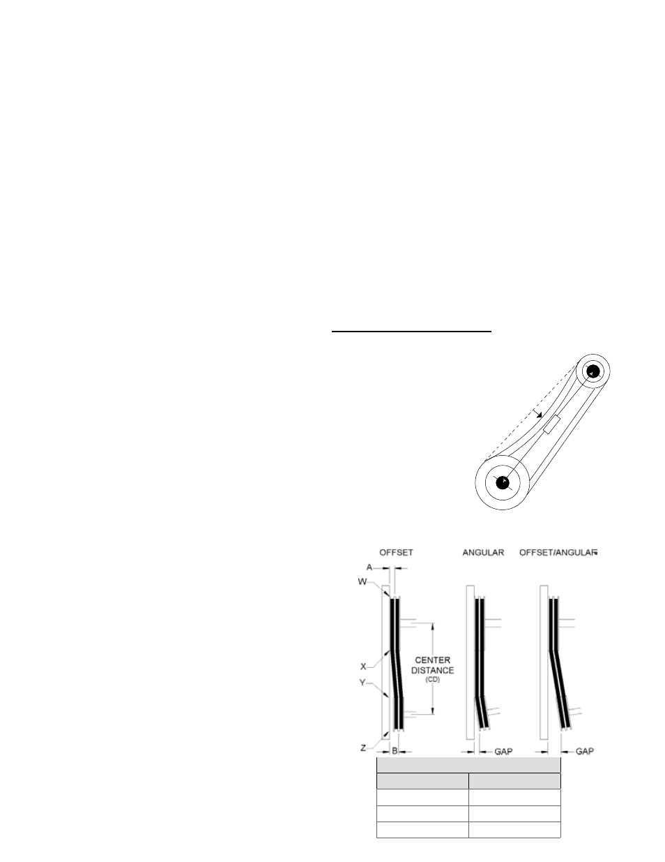
1 foot
1/4 inch
Tolerance
Center Distance
Maximum Gap
Up thru 12”
1/16”
12” up through 48
1/8”
Over 48”
1/4”