Operation – COOK HMD EN User Manual
Page 4
4
holes.
3. Connect the main power lines to the disconnect
switch and main grounding lug(s). Torque field
connections to 20 in.-lbs.
4. Wire the optional convenience outlet. The
convenience outlet requires a separate 115V power
supply circuit. The circuit must include short circuit
protection which may need to be supplied by others.
Single Phase
When ground is required, attach
to ground A or B with no. 6
thread forming screw. To reverse,
interchange T-1 and T-4
Three Phase
A complete wiring diagram is attached on
the inside of the control center door(s). It is
also available in the HMD Wiring Diagram
Supplement.
Gas
All gas piping must be installed in accordance
with local codes, or in the absence of local
codes, in accordance with the National Fuel
Gas Code, ANSI 2223.1/NFPA 54, or the
CAN/CSA B149.1 Natural Cas and Propane
Installation Code.
Do not connect the unit to gas types other than
what is specified and do not connect the unit to gas
pressures that are outside of the pressure range
shown on the label.
When connecting the gas supply, the length
of the run must be considered in determining
the pipe size to avoid excessive pressure drop.
Refer to a Gas Engineer’s Handbook for gas
pipe capacities.
Refer to the heater rating plate for determining
the minimum gas supply pressure for obtaining
the maximum gas capacity for which this heater
is specified.
1. Determine the supply gas requirements by looking
at the unit’s nameplate on the outside of the unit on
the control center side.
2. When the supply gas pressure exceeds the maximum
gas pressure shown on the nameplate, an additional
regulator (by others) is required to reduce the
pressure. The regulator must have a listed leak
limiting device or it must be vented to the outdoors.
The regulator located inside the unit is used to adjust
the unit’s maximum output temperature.
3. If an optional vent line is located between the safety
shutoff valves it must be piped to the outdoors.
Reference the National Fuel Gas Code for
additional vent line requirements.
4. Test the system for leaks.
Operation
Pre Start-Up
Follow the pre start-up list before
proceeding. Follow the procedure in the
exact order that it is presented.
Failure to do so could result in serious injury
or death and damage to equipment.
Pre Start-Up:
General
1. Get: voltage & amperage meter, thermometer, micro
amp meter, u-tube manometer & tachometer.
2. Perform a gas leak check during heater start-up, to
verify the gas tightness of the heater’s components
and piping under normal operating conditions.
3. Disconnect and lock-out all power and gas.
Blower
1. Check the housing, blower, and ductwork for any
foreign objects before running the blower.
2. Rotate the fan wheel by hand and make sure no
parts are rubbing. Check the V-belt drive for proper
alignment and tension (a guide for proper belt tension
and alignment is provided in the Belt Maintenance
section).
3. Check fasteners, set screws and locking collars on
the fan, bearings, drive, motor base, and accessories
for tightness.
4. Compare the supplied voltage, hertz, and phase with
the unit and motor’s nameplate information.
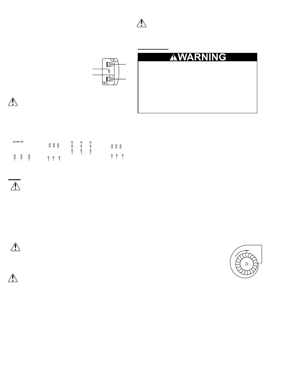
5. Open the blower access door and run
the blower momentarily to determine
the rotation. Arrows are placed on the
blower scroll to indicate the proper
direction.
NOTICE! If the blower is rotating in
the wrong direction, the unit will move
some air, but will not perform as designed. Be sure
to perform a visual inspection to guarantee the
correct blower rotation.
• To reverse the rotation on three phase units,
disconnect and lock-out the power, then interchange
any two power leads.
• To reverse the rotation on single phase units,
disconnect and lock-out the power, then rewire the
motor per the motor manufacturer’s instructions.
6. Check for unusual noise, vibration or overheating
of the bearings. Reference the Troubleshooting
section for corrective actions. Excessive vibration
T-1
T-4
Ground B
L 2
L1
Ground A
Line
4 5 6
1
7
2
8
3
9
L1 L2 L3
4 5 6
7 8 9
1 2 3
L1 L2 L3
Low Voltage
208/230 Volts
High Voltage
460 Volts
3 Phase, 9 Lead Motor
Y-Connection
7
1
6
7 8 9
4 5 6
1 2 3
Low Voltage
208/230 Volts
High Voltage
460 Volts
8
2
4
9
3
5
L1
L3
L2
L1
L3
L2
3 Phase, 9 Lead Motor
Delta-Connection