COOK HMD EN User Manual
Page 5
5
may be experienced during the initial start-up. Left
unchecked, it can cause a multitude of problems
including structural and/or component failure.
Generally, fan vibration and noise is transmitted
to other parts of the building by the ductwork. To
minimize this undesirable effect, the use of heavy
canvas duct connectors is recommended.
7. Measure the motor’s voltage, amps and RPM.
Compare to the specifications. Motor amps can be
reduced by lowering the motor RPM or increasing
system static pressure. Additional starters and
overloads may be provided in the make-up air
control center for optional exhaust blowers. Any
additional overloads must be checked for proper
voltage and amps.
8. Measure the unit’s air volume (cfm) and compare
it with its rated air volume. If the measured air
volume is wrong, adjust the fan’s RPM by changing/
adjusting the drive. The most accurate way to
measure the air volume is by using a Pitot traverse
Testing Inspection
All components of this or any other gas-
fired heating unit must be leak tested prior
to placing the unit into operation. The
factory piping has been checked for leaks
but should be rechecked due to shipping &
installation issues. The field-installed shutoff
valve should also be checked.
A soap & water solution should be used to
perform this test.
Never test for gas leaks with a flame.
When leak testing pressures that are less
than or equal to 14 in. wc (3.5 kPa), first
close the field-installed shutoff valve to
isolate the unit from gas supply line.
When leak testing presures that are more
than 14 in. wc (3.5 kPa), close the field-
installed shutoff valve, disconnect the
furnace & gas train from the gas supply line
& plug the supply line before testing.
All piping should be clean & free of any
foreign matter, which may damage the
values, regulators or burner.
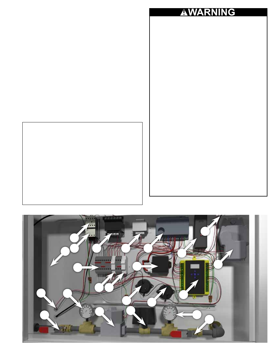
Control Panel
Control Panel Parts
1. Contactor
2. Overload
3. Three phase
transformer #A
4. 120 - 24v
transformer #B
5. Ignition control
6. High Temp Overload
7. Mild weather thermostat
to damper
8. Damper motor
9. Terminal blocks
10. Circuit breaker
11. Override switch
12. 120v spark ignitor
13. Pressure sensing probe
(high)
14. Pressure sensing probe
(low)
15. Temperature controller
16. Thermostat to blower
17. Safety Shut off valve
18. Pressure gauge
19. Gas valve
20. Modulating gas valve
21. Pressure gauge
22. Safety Shut off valve
23. Optional V.F.D. here
1
2
3
4
5
6
7
8
9
12
10 11
15
13
17
16
18
19
22
20
21
14
23