COOK HMD EN User Manual
Page 3
3
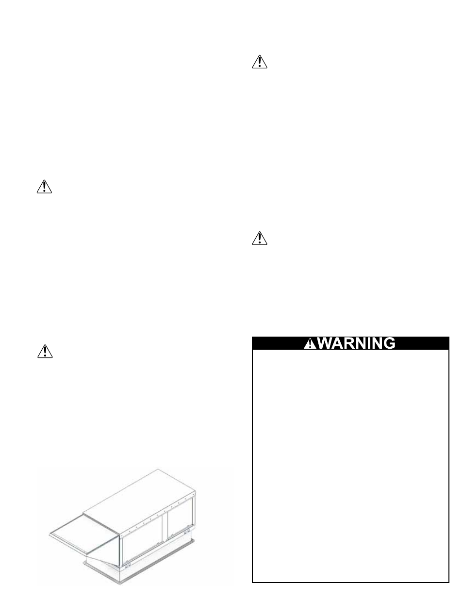
attached to the unit.
8. Using an appropriate sealant, seal the seam
between the weatherhood and the unit.
Wiring
All wiring should be done in accordance with
the latest edition of the National Electric Code
ANSI / NFPA 70 and any local codes that may
apply. In Canada, wiring should be done in
accordance with the Canadian Electrical Code.
NOTICE! The equipment must be properly
grounded. Any wiring running through the unit in
the airstream must be protected by metal conduit,
metal clad cable or raceways.
NOTICE! If any of the original wire as supplied with
the heater must be replaced, it must be replaced
with type TW1 600v wire or its equivalent.
NOTICE! Field-wiring having a temperature rating
of at least 105ºC shall be used and supply circuit
wiring shall have a minimum size of 14 AWG.
NOTICE! High voltage electrical input is needed for
this equipment.
An electric disconnect switch having adequate
ampacity (see marking on the heater for
voltage and ampacity), if not provided as part
of the heater, shall be installed in accordance
with Article 430 of the National Electrical Code,
ANSI/NFPA 70.
1. The unit’s nameplate states the voltage and the
unit’s MCA. The main power lines to the unit should
be sized accordingly. The nameplate is located on
the outside of the unit on the control panel side.
2. Install field electrical wires through the provided
Custom work
Any wiring deviations may result in personal
injury or property damage. Manufacturer
is not responsible for any damage to, or
failure of the unit caused by incorrect final
wiring.
Manufacturer’s standard control voltage is
120 VAC. Control wire resistance should not
exceed 0.75 ohms (approximately 285 feet
total length for 14 gauge wire; 455 feet total
length for 12 gauge wire). If the resistance
exceeds 0.75 ohms, an industrial-style
plug-in relay should be wired in place of
the remote switch. The relay must be rated
for at least 5 amps and have a 120 VAC
coil. Failure to comply with these guidelines
may cause motor starters to chatter or not
pull in, resulting in contactor failures and/or
motor failures.
of each threaded hanger. Ceiling supports are not
supplied.
2. Using sheet metal screws, attach the weatherhood/
thru-wall / filter section to the damper / burner
section. The flange on the weatherhood / thru-wall
/ filter section should overlap the flange on the
damper / burner section.
3. Raise the unit into place
4. Using two nuts per hanger, fasten the unit supports
to the hangers under the unit. Appropriate unit
supports, such as the optional hanging bracket kit
or c-channel and angle iron (not included) should be
used.
5. Attach ductwork to unit using self-tapping screws
NOTICE! In order to prevent the unit from swinging
and to provide a safe environment for service and
maintenance, additional measures may be needed to
secure the unit.
Good duct practices should be followed for
all ductwork. Ductwork should be installed
in accordance with SMACNA and AMCA
guidelines, NFPA 96 and any local codes.
NOTICE! When a duct work system is attached to
the inlet of the heater purge the volume of the duct
system with at least four air changes prior to an
ignition attempt.
6. Apply sealant around the perimeter of the
weatherhood to prevent water penetration and drafts
into the building.
Curb Arrangement
1. Position curb on the roof. Verify that unit supports
are level, shim if necessary.
2. Attach curb to roof, flash in place
3. Attach ductwork to unit using self-tapping screws
Good duct practices should be followed for
all ductwork. Ductwork should be installed
in accordance with SMACNA and AMCA
guidelines, NFPA 96 and any local codes.
4. Apply an appropriate sealant around the perimeter
of the curb and duct adapter(s) to isolate fan
vibration and prevent water penetration
5. Use the 4 lifting lugs to lift and place unit on the
curb. A crane with a spreader bars is required.
6. NOTICE! Do not include a wood nailer. Use self-
tapping sheet metal screws to fasten the unit to the
curb support.
7. The weatherhood can now be assembled and
Curb Mount Example