HID VertX EVO V1000 Installation Guide User Manual
Page 7
VertX EVO V1000 Installation Guide
CAUTION: The V1000 RS-485 Ports 1 & 2 (P3) are a common bus and therefore cannot have panels with
duplicate Interface Addresses assigned. The same is true of the V1000 RS-485, Ports 3 & 4 (P4). For
example, two panels, both with Interface Address 0 (factory default), cannot be connected to Ports 1
and/or 2 (P3).
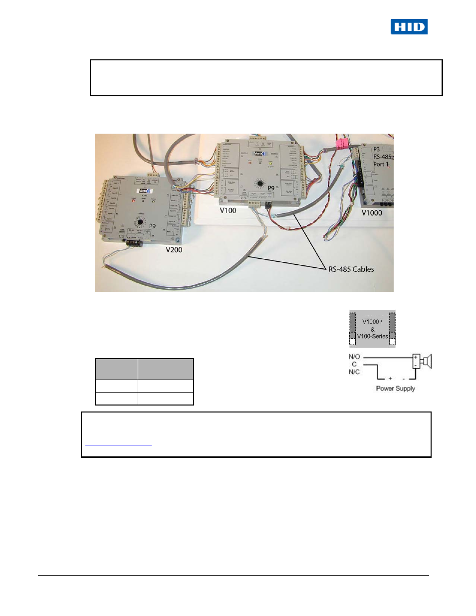
Wire the RS-485 to the In position only of the P9 terminal block for the V100-Series panel. This is especially
important when the RS-485 communication is in a “daisy chain” configuration. If the RS-485 is wired In and Out,
and power is lost, or the P9 terminal block is unplugged on a V100-Series panel, RS-485 communications will be
lost to downstream V100-Series panels.
4. Output Connections (VertX EVO V1000) –
All Output connections are used for general purpose controls. The following
table shows where the various outputs are located. Pin numbers shown use the
convention “NO/C/NC”. For example, Output 1, V1000: P14 Pin 3 is NO
(Normally Open,) Pin 4 is C (Common,) and
Pin 5 is NC (Normally Closed).
Note:
Relays are dry contact rated for 2Amps @ 30VDC.
Output
number
V1000
1
P14 Pins 3/4/5
2
P11 Pins 3/4/5
CAUTION: Some magnetic locks exhibit both high inrush current when activated and a high
instantaneous break voltage when de-energized due to magnetic field collapse. Use a snubber circuit
across the controlling relay terminals to protect the controlling relay contacts. Go to
support.hidglobal.com
, see Solution 891 - How do I wire a High In-Rush Current locking device to
VertX/Edge/Edge Solo?.
July 2011
Page 7 of 19
© 2003 - 2011 HID Global Corporation. All rights reserved.