2 - mounting, 3 - wiring, Mounting – HID EDGE EVO Solo ESH400-K Networked Controller Installation Guide User Manual
Page 5: Wiring, Standard networked controller
82000-921, D.1
INSTALLATION GUIDE
5
©2009 - 2012 HID Global Corporation. All rights reserved.
Standard Networked Controller
EH400-K
Hi-O Group Select Jumper
Short = Group 1, Open = Group 2
Outside Door
Inside Door
( )
1
P2
12
1
P1
4
CAN V+
GND
CAN_H
CAN_L
RDR PWR
GND
Data0 / Data
Data1 / CLK
*
GRN LED
RED LED
Hold
*
Beep
GRP SEL
+
-
10
P3
14
P1
1
+
-
Hi-O Group Select Jumper
Short = Group 1, Open = Group 2
Outside Door
Inside Door
( )
+
-
*
NC
NO
COM
NC
NO
COM
Relay Jumpers
6
P1
0
1
AUX
+DC
AUX
GND
+
-
Reader Tamper +
Door Strike
AU
X
AC FAIL
INPUT SENSE
REX
Door Mon
* = Internal Optical Tamper Disable
BATT FAIL
INPUT SENSE
Note: Connect the Door Monitor to avoid a Force Door Alarm.
P9 P5 P8 P6 P4 P7
Ethernet / PoE
Auto-Detected
Activity LED
Link LED
Hi-O CANbus
Reader Tamper -
CAP
Restore Network
Defaults Jumper
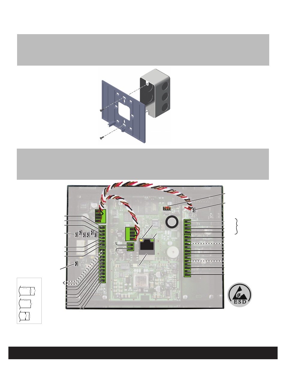
2
Mounting
Junction box not included.
Wiring
3
CAUTION: Some magnetic locks exhibit both high inrush current when activated and a high instantaneous break voltage
when de-energized due to magnetic field collapse. It is recommended you use of a snubber circuit across the controlling relay
terminals to protect the controlling relay contacts. Go to support.hidglobal.com, see Solution 891 - How do I wire a High In-
Rush Current locking device to VertX/EDGE EVO. Not evaluated by UL.
Optional
Supervised Inputs
1-6K
N/O
1-6K
N/C
1-6K
1-6K
N/O
ATTENTION
Observe precautions for handling
ELECTROSTATIC SENSITIVE DEVICES