Relay switch connection diagram – Swiftech H20KITS User Manual
Page 4
1703 E. 28
th
St., Signal Hill, CA 90755
Tel (562) 595-8009 - Fax (562) 595-8769
URL: HTTP://WWW.SWIFTNETS.COM
4
5/ Electrical Installation
Find a suitable placement for the pump’s A/C
socket. Leave sufficient room under or above
the hole to install the pump relay switch circuit
board. A ¼” minimum clearance will be required
between the circuit board and the edge of the
hole.
Make a 1.25” (32mm) diameter hole in
the case, using a 1 ¼” Bi-Metal hole saw.
Deburr the edges of the hole with sand
paper.
Position and center the mounting plate
over the hole as a template to mark the
locations of the plate’s mounting screws.
Drill 2 holes of .125” diameter for the
mounting screws. Install the mounting
plate using the screws provided with your
kit.
Insert the A/C socket inside the mounting plate
Pump’s
relay switch
circuit board
A/C
Socket
1.
25
"
Ho
le
Sp
aci
ng
N\O
+
_
0.
25
"
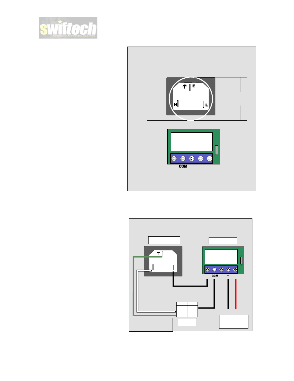
Proceed with electrical connections as
described in the diagram to the right.
For normal operations, the L wire from the A/C
socket must be connected to the N/O (normally
opened) position of the switch. Normally Opened
means that when the computer is off, and there is
no current from the power supply going to the
switch, the relay is opened, disallowing A/C to
the pump. Conversely, as soon as you turn the
computer on, the switch becomes energized by
the power supply, and the relay closes, allowing
A/C current to pass to the pump.
E
N
L
Ground +12v
Relay switch connection diagram
N\O
+
A/C Socket
Pump
Computer
Power Supply
Relay switch
US Europe
Black Brown
White Blue
Green Yellow
WARNING! Always disconnect
from A/C power source while
working with electrical devices.