Swiftech H20 120 PREMIUM User Manual
Page 22
Copyright Swiftech 2005 – All rights reserved – Last revision date: 09-22-06 - Information subject to change without notice – URL:
http://www.swiftnets.com
Rouchon Industries, Inc., dba Swiftech – 1703 E. 28
th
Street, Signal Hill, CA 90755 – Tel. 562-595-8009 – Fax 562-595-8769 - E Mail: [email protected]
PAGE 22 of 26
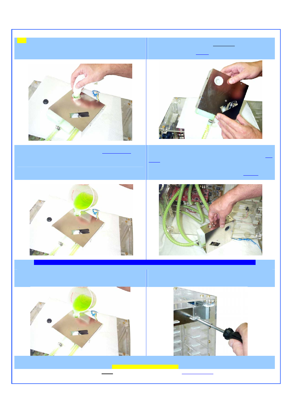
TIP!
If you overfill the reservoir, you can use a bundled-up paper towel to
soak-up the excess fluid.
Step 4. Tilt the assembly upwards to allow the fluid to fill-up the circuit by
simple gravity. Allow the fluid to fill-up both tubes. The pump
discharge line will retain a 2” long bubble, which is normal at this
stage. See troubleshooting
note (1)
if the pump discharge tube does not
fill-up properly.
Step 5. Rest the assembly back on top of the computer, and complete
filling-up the reservoir until the fluid reaches the
appropriate level
. Close
the fill port with the provided fill-cap. Do not over tighten the fill-cap. The
fill-cap is equipped with an o-ring and does not require excessive pressure
to seal properly.
Step 6. Rest the assembly on its side, down on your workbench and
connect the pump Molex connector to the power supply. You must be
able to start the PSU without it being connected to the motherboard (
See
Note 2
). Start-up the PSU. The pump has a 3 Seconds delay before it
start running. Observe the flow circulating throughout the circuit, until all
the bubbles disappear. DO NOT OPERATE THE PUMP IF THERE IS
NO CIRCULATION, and refer to troubleshooting
note (1)
before
proceeding any further.
.
A
LLOW THE SYSTEM TO RUN FOR
(3)
HOURS
,
AND FREQUENTLY INSPECT ALL YOUR CONNECTIONS FOR POSSIBLE LEAKS
.
Step 7. Rest the assembly back on top of the computer, and complete
filling-up the reservoir as necessary. You may slightly angle (approx. 15°)
the reservoir to top-off the fluid level, by placing a small object under the
reservoir.
Step 8. Install the assembly in the desired CR Rom bay, and secure with
the provided standard M3 screws. The MCRES-1000P is designed to be
recessed from the front panel, and allow clearance for various cover
plates or fan controllers.
Step 9. Connect the pump’s 4 pin Molex connector to the computer PSU, and the 3-pin connector (RPM sensor) to the CPU fan header on the
motherboard. INSTALLATION IS NOW COMPLETE!