Allied Telesis AT-8288XL/SC User Manual
Page 59
AT-8216FXL, AT-8224XL, and AT-8288XL Series Installation Guide
59
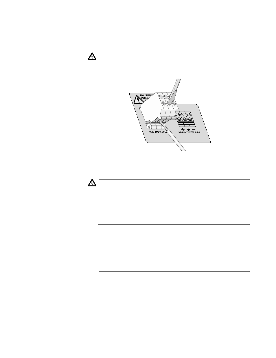
3. Connect the frame ground wire to the terminal marked with the
ground symbol by inserting the wire into the terminal and tightening
the connection with a flathead screwdriver.
Warning
When installing this equipment, always ensure that the frame
ground connection is installed first and disconnected last.
" 6
4. Connect the positive feed to the terminal block marked + (plus).
5. Connect the negative feed to the terminal block marked - (minus).
Warning
"Safety Hazard"- Check to see if there are any exposed copper
strands coming from the installed wires. When this installation is
done correctly, there should be no exposed copper wire strands
extending from the terminal block. Any exposed wiring can
conduct harmful levels of electricity to persons touching the wires.
" 22
6. Secure the tray supply cable near the rack framework using multiple
cable ties to minimize the chance of the connections being disturbed
by casual contact with the wiring. Use at least four cable ties
separated four inches apart with the first one located within six inches
of the terminal block.
Note
This system will work with a positive grounded or negative
grounded DC system.
" 23
This completes the procedure for connecting the LAN equipment to a
DC power source.