Port leds, Station port leds, Hardware description 22 – Allied Telesis AT-8288XL/SC User Manual
Page 22
Hardware Description
22
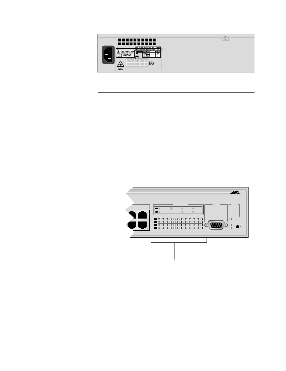
Figure 7 shows the switch’s back panel with the AC connector.
Figure 7 Back Panel
Note
The AT-D8224XL switch has a DC power terminal block on the back
panel.
Port LEDs
Each switch port has two LEDs that indicate the following:
# L/A LED - indicates a valid physical link with a device with packets
being received/transmitted and speed of transmission
# D/C LED - indicates half- or full-duplex and collisions
Figure 8 shows the LEDs on the AT-8224XL switch. (Port LEDs
for an AT-8216FXL switch are located above each port. Port
LEDs for an AT-8288XL switch are located next to each port.)
Figure 8 Port LEDs
For more details about the LEDs, refer to Table 3, Switch System LED
STATUS
RESET
FAULT
RPS
PWR
1
2
3
4
5
6
7
8
9
10
11
12
13
14
15
16
17
18
19
20
21
22
23
24
10BASE-T / 100BASE-TX
7X
8X
9X
11X
13X
15X
10X
12X
14X
16X
17X
19X
21X
23X
18X
20X
22X
24X
RS-232
TERMINAL PORT
100M LINK / ACTIVITY
10M LINK / ACTIVITY
HALF DUP/ COL
FULL DUP
PORT ACTIVITY
L /A
L /A
D/C
D/C
L /A
D/C
Station Port LEDs