Switch leds, E leds, refer to table 3, switch system led – Allied Telesis AT-8288XL/SC User Manual
Page 41
AT-8216FXL, AT-8224XL, and AT-8288XL Series Installation Guide
41
Switch LEDs
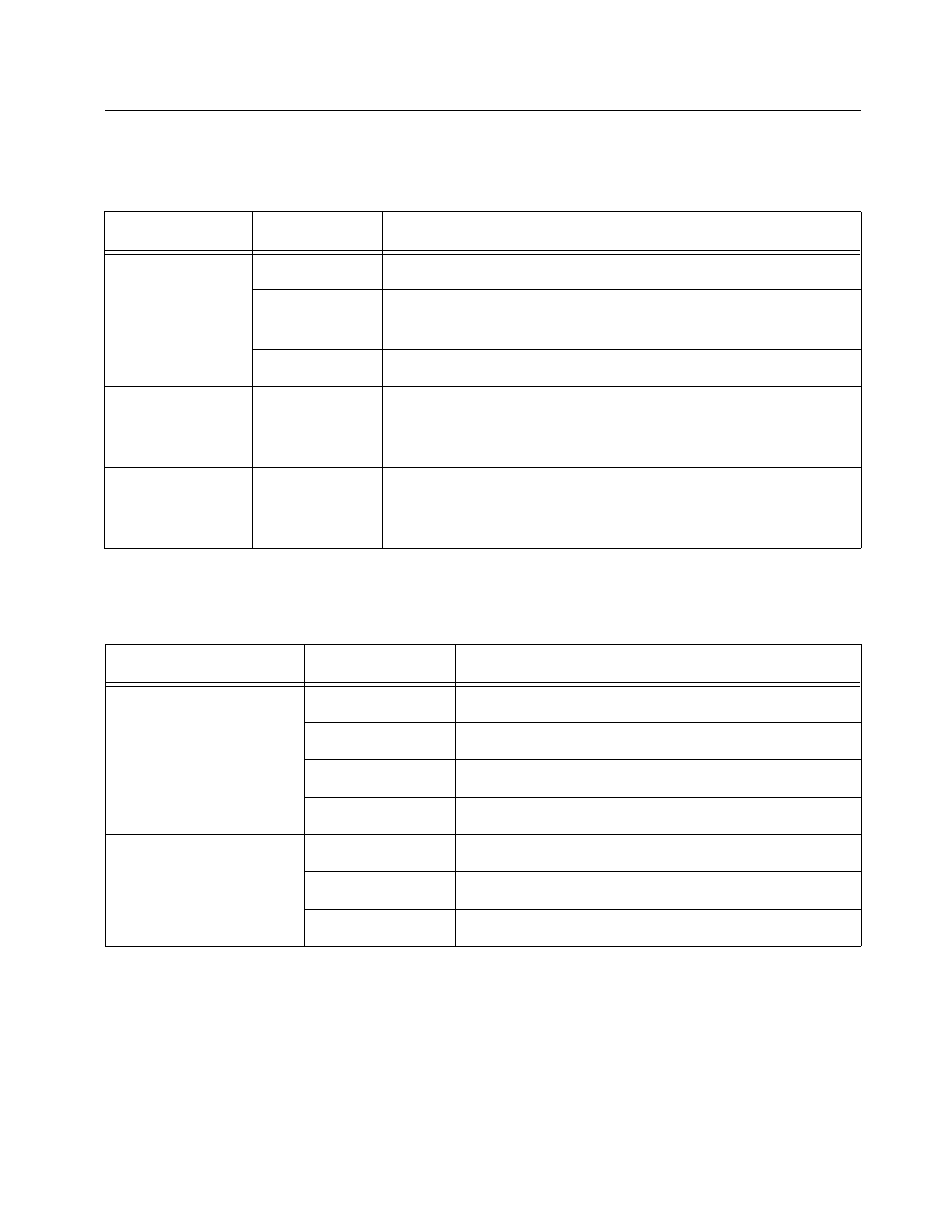
Table 3 describes the system LEDs on the Ethernet switch.
Table 4 describes the port LEDs on the Ethernet switch.
Table 3 Switch System LED Status
LED
State
Description
Fault
Solid Red
The switch or management software is malfunctioning.
Flashing Red
The switch is booting, running diagnostic tests, writing
messages to FLASH, or transferring files using XMODEM.
OFF
Normal operation.
PWR (Power)
Solid Green
The switch is receiving power, the voltage is within the
acceptable range, and the main power supply or the
optional redundant power supply is working.
RPS (Redundant
Power Supply)
Solid Green
An optional redundant power supply is connected to the
switch. (This LED will remain lit even when the optional
redundant power supply is powered OFF.)
Table 4 Port LED Status
LED
State
Description
L/A (Link/Activity)
Solid Green
This indicates a 100 Mbps link.
Flashing Green
This indicates 100 Mbps activity.
Solid Amber
This indicates a 10 Mbps link (10/100 ports only).
Flashing Amber
This indicates 10 Mbps activity (10/100 ports only).
D/C (Duplex/Collision)
Solid Green
The port is operating at full-duplex.
Solid Amber
The port is operating at half-duplex.
Flashing Amber
Collisions are occurring on the line.