Board card guide – Allied Telesis AT-8288XL/SC User Manual
Page 39
AT-8216FXL, AT-8224XL, and AT-8288XL Series Installation Guide
39
If you are installing only one expansion module in the switch, you
should install the module in slot A (upper slot). While the module
will work in slot B (bottom slot) with slot A empty, the port
numbering assignments will change if you later install a module in
slot A. This could affect the VLAN memberships on the switch and
this could require you to adjust your VLAN configurations.
For example, if you install an AT-A17 expansion module in slot B
of an AT-8224XL switch while leaving slot A empty, the switch will
assign the port numbers 25 and 26 to the ports on the module. If
you later install another AT-A17 module in slot A, the switch will
automatically reallocate port numbers 25 and 26 to the new
modules in slot A and assign the port numbers 27 and 28 to the
module in slot B. If the module in slot B had been a member of a
VLAN, you would be required to reconfigure the VLAN to reflect
the change to its port numbers.
3. Remove the expansion module from the packing material. Be sure
you observe ESD precautions.
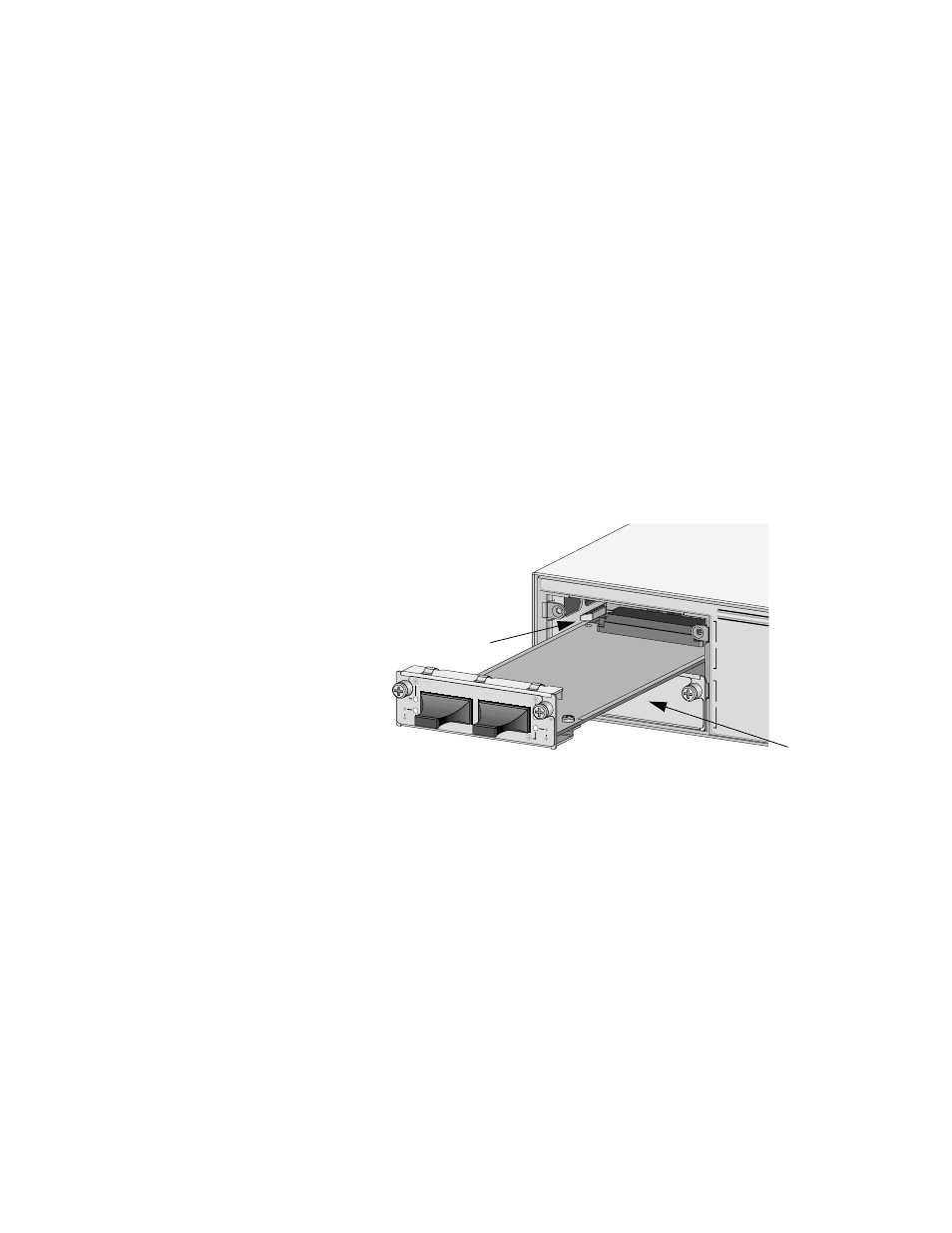
4. Slide the expansion module into the empty slot making sure the
board is aligned properly with the card guides. Refer to Figure 16.
Figure 16 Installing an Expansion Module
5. Secure the expansion module to the switch by tightening the captive
screws.
6. Apply power to the switch by re-attaching the power cord to the
switch. Verify that the Power LED is green.
7. Connect the data cable(s) to the port(s) on the module.
8. Verify the LEDs on the expansion module’s front panel by referring to
the quick install guide included with the module.
9. Go to the procedure ‘Setting Up a Terminal for Local Management’
on page 40 for instructions on how to access the Omega
management software interface on the switch.
A
B
AT-A17
100BASE-FX/SC
RX
TX
RX
TX
LINK
ACTIVITY
FULL DUP
HALF DUP
COL
LINK
ACTIVITY
FULL DUP
HALF DUP
COL
1
2
Board
Card Guide