Connectors and port pinouts – Allied Telesis AT-x210-9GT User Manual
Page 64
Appendix A: Technical Specifications
54
Connectors and Port Pinouts
This section lists the connectors and connector pinouts.
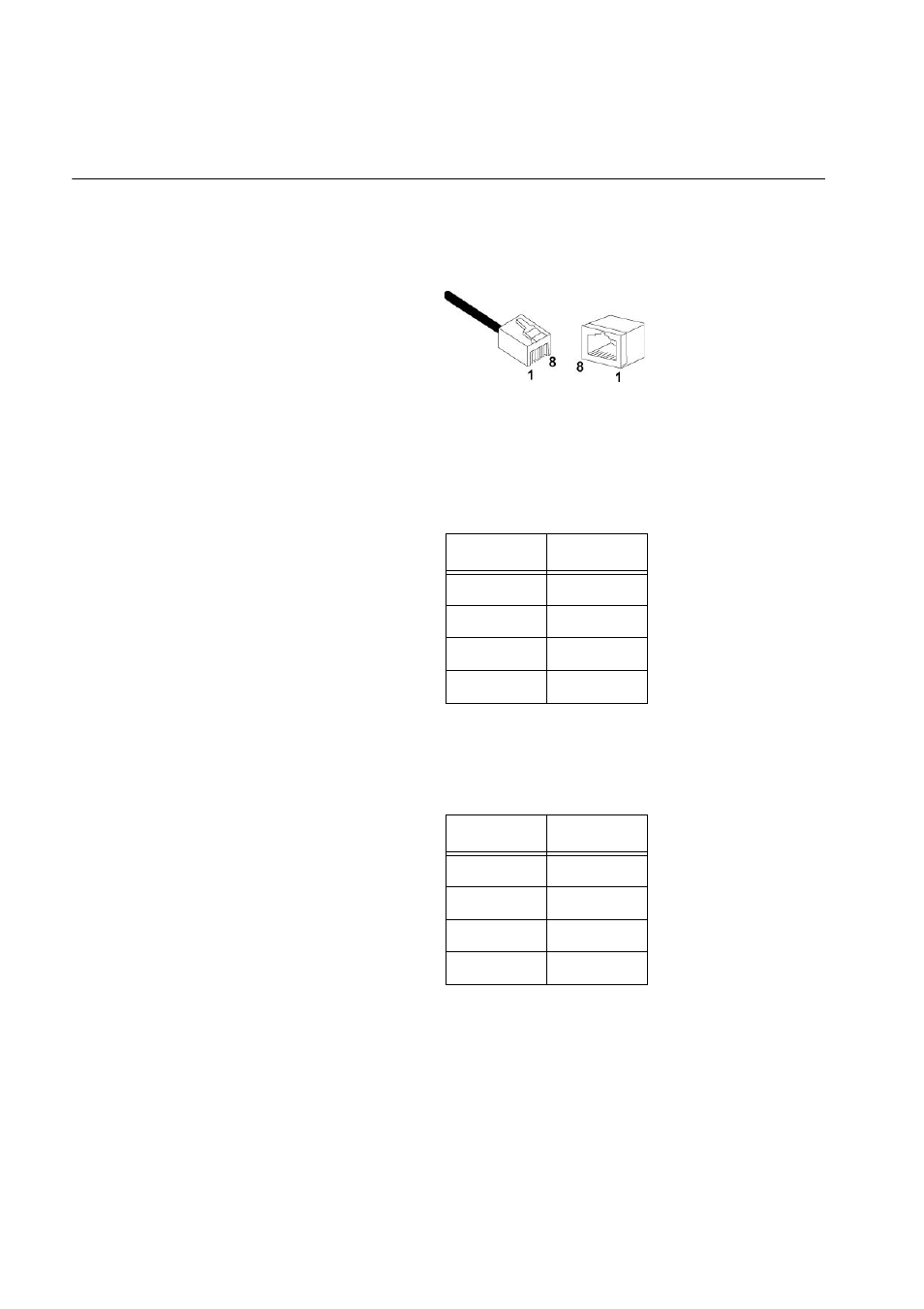
Figure 37 illustrates the pin layout for an RJ-45 connector and port.
Figure 37. RJ-45 Connector and Port Pin Layout
Table 13 lists the RJ-45 pin signals when a twisted pair port is operating in
the MDI configuration.
Table 14 lists the RJ-45 port pin signals when a twisted pair port is
operating in the MDI-X configuration.
Table 13. MDI Pin Signals (10Base-T or 100Base-TX)
Pin
Signal
1
TX+
2
TX-
3
RX+
6
RX-
Table 14. MDI-X Pin Signals (10Base-T or 100Base-TX)
Pin
Signal
1
RX+
2
RX-
3
TX+
6
TX-
This manual is related to the following products: