Allied Telesis AT-x210-9GT User Manual
Page 43
AT-x210-9GT, AT-x210-16GT, and AT-x210-24GT Switches Installation Guide
33
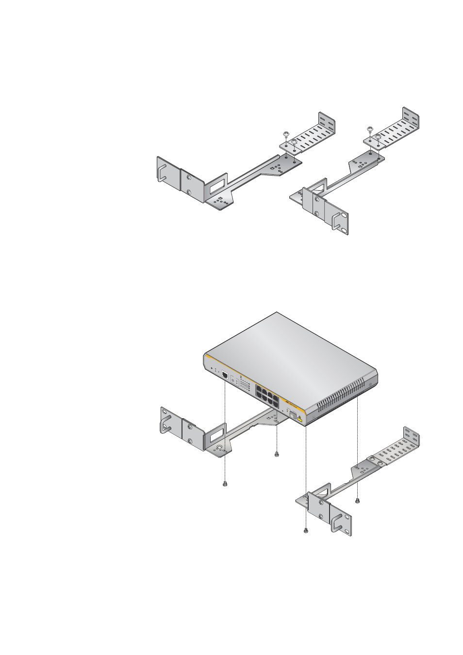
9. Next attach the cable tray brackets for AT-x210-9GT switches, as
Figure 23. Attaching cable tray brackets for an AT-x210-9GT
10. Mount an AT-x210-9GT switch in a 19-inch equipment rack, as shown
below in Figure 24, using the screws from the rubber feet after
removing these screws, as shown earlier in Figure 15.
Figure 24. Mounting an AT-x210-9GT Switch in an Equipment Rack
1
3
5
7
2
4
6
8
FA
UL
T
ST
ANDBY
RESET
POWER
CONSOLE
RS-232
MODE
SPEED
DUPLEX
SELECT
2
4
6
8
1
3
5
7
L/A
MODE
L/A
MODE
9
AT-x210-9GT
Gigab
it Ether
net Sw
itch
CL
ASS 1
LASER PRODUCT
MODE
SPEED / DUPLEX
L/A
LINK /
ACT
L/A
LINK /
ACT
SFP
This manual is related to the following products: