Allied Telesis AT-x210-9GT User Manual
Page 44
Chapter 2: Installation
34
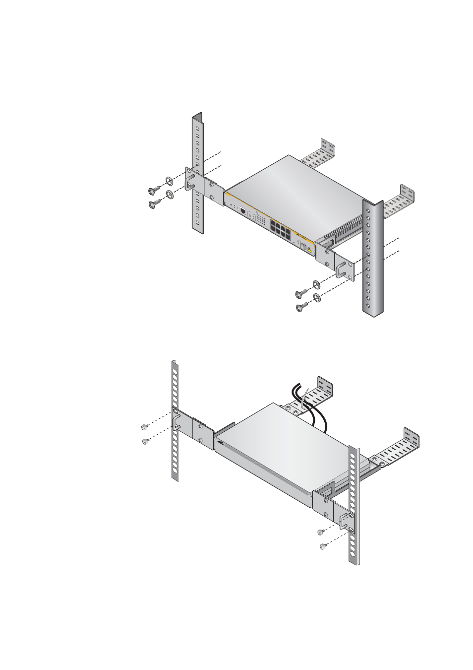
11. Mount an AT-x210-9GT switch in a 19-inch equipment rack using the
provided spacer bracket mounts with four equipment rack screws, as
shown in Figure 25.
Figure 25. Mounting an AT-x210-9GT Switch in an Equipment Rack
12. Secure cables to the cable tray fitted earlier, as shown in Figure 26.
Figure 26. Securing cables to the cable tray for an AT-x210-9GT
1
3
5
7
2
4
6
8
FA
UL
T
ST
ANDBY
RESET
POWER
CONSOLE
RS-232
MODE
SPEED
DUPLEX
SELECT
2
4
6
8
1
3
5
7
L/A
MODE
L/A
MOD
E
9
AT-x210-9GT
Gigab
it Ether
net Sw
itch
CLA
SS 1
LA
SER PR
ODU
CT
MO
DE
SP
EED / DUPLEX
L/A
LINK /
ACT
L/A
LI
NK /
ACT
SFP
This manual is related to the following products:
See also other documents in the category Allied Telesis Computer hardware:
- AT-GS908M (54 pages)
- AT-x230-10GP (80 pages)
- AT-GS950/48PS (64 pages)
- AT-GS950/10PS (386 pages)
- AT-GS950/16PS (386 pages)
- AT-GS950/48PS (386 pages)
- AT-9000 Series (258 pages)
- AT-9000 Series (1480 pages)
- IE200 Series (70 pages)
- AT-GS950/48 (410 pages)
- AT-GS950/8 (52 pages)
- AT-GS950/48 (378 pages)
- AT-GS950/48 (60 pages)
- SwitchBlade x8106 (322 pages)
- SwitchBlade x8112 (322 pages)
- SwitchBlade x8106 (240 pages)
- SwitchBlade x8112 (240 pages)
- AT-TQ Series (172 pages)
- AlliedWare Plus Operating System Version 5.4.4C (x310-26FT,x310-26FP,x310-50FT,x310-50FP) (2220 pages)
- FS970M Series (106 pages)
- 8100L Series (116 pages)
- 8100S Series (140 pages)
- x310 Series (116 pages)
- x310 Series (120 pages)
- AT-GS950/24 (404 pages)
- AT-GS950/24 (366 pages)
- AT-GS950/16 (44 pages)
- AT-GS950/16 (404 pages)
- AT-GS950/16 (364 pages)
- AT-GS950/8 (52 pages)
- AT-GS950/8 (404 pages)
- AT-GS950/8 (364 pages)
- AT-8100 Series (330 pages)
- AT-8100 Series (1962 pages)
- AT-FS970M Series (330 pages)
- AT-FS970M Series (1938 pages)
- SwitchBlade x3106 (288 pages)
- SwitchBlade x3112 (294 pages)
- SwitchBlade x3106 (260 pages)
- SwitchBlade x3112 (222 pages)
- AT-S95 CLI (AT-8000GS Series) (397 pages)
- AT-S94 CLI (AT-8000S Series) (402 pages)
- AT-IMC1000T/SFP (23 pages)
- AT-IMC1000TP/SFP (24 pages)
- AT-SBx3106WMB (44 pages)