Position of the switch on the wall, Recommended minimum wall area dimensions – Allied Telesis x310 Series User Manual
Page 73
x310 Series Installation Guide for Stand-alone Switches
73
Installing the AT-x310-26FP, AT-x310-50FT, and AT-x310-50FP
Switches on a Wall
This section contains the instructions for installing the AT-x310-26FP, AT-
x310-50FT, and AT-x310-50FP Switches on a wall.
Position of the
Switch on the
Wall
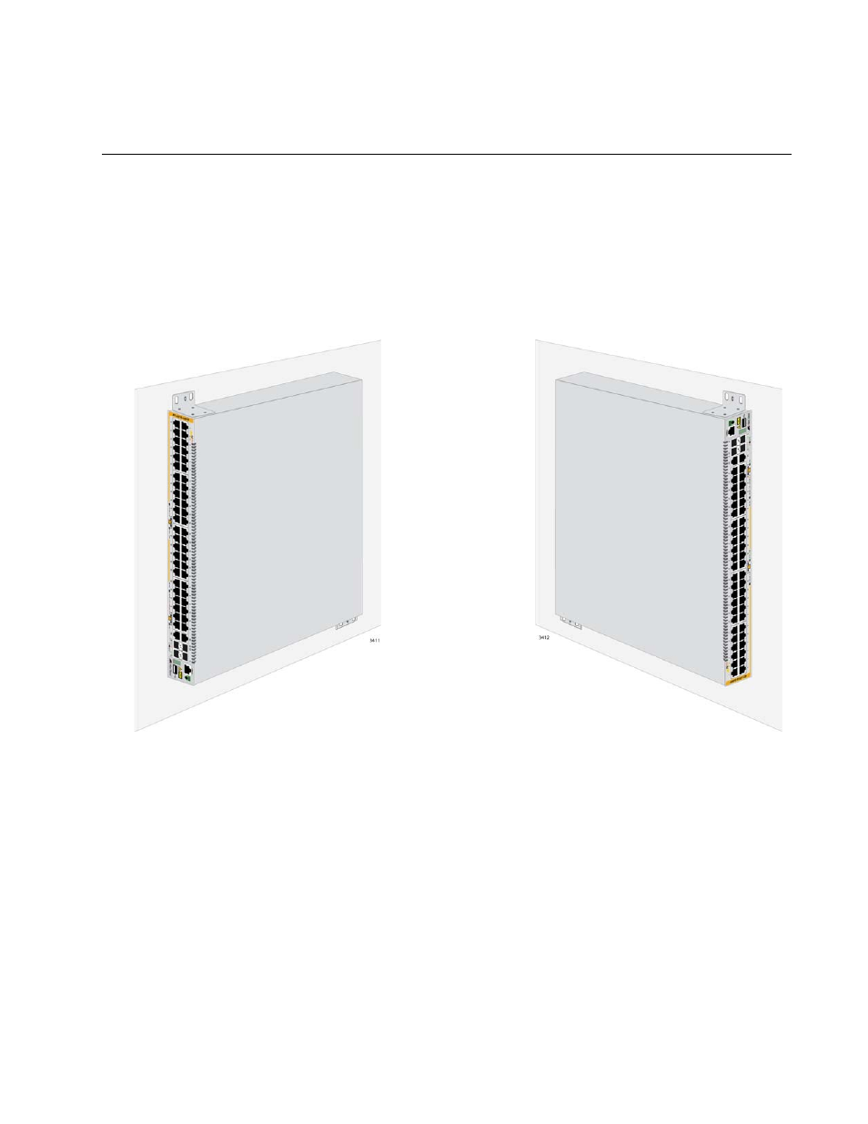
The switch may be installed on the wall with the front panel on the left or
right, as shown in Figure 29. You may not install the switch with the front
panel on the top or bottom.
Figure 29. Positions of the AT-x310-26FP, AT-x310-50FT, and AT-x310-
50FP Switches on a Wall
Recommended
Minimum Wall
Area Dimensions
The recommended minimum dimensions for the reserved wall area for the
AT-x310-26FP, AT-x310-50FT, and AT-x310-50FP Switches are listed
here:
Width: 68.0 centimeters (27 inches)
Height: 58.4 centimeters (23 inches)
The placement of the switch in the reserved area should provide the front
panel with more area than the back panel so that you can connect network
cables, install SFP modules, and view port LEDs. Figure 30 on page 74
shows the recommended position of the switch in the reserved area when