2 rs-232 wiring, 3 analog 0 to 5 volt wiring, Rs-232 wiring – Campbell Scientific OBS500 Smart Turbidity Meter with ClearSensor Technology User Manual
Page 28: Analog 0 to 5 volt wiring, 5. rs-232 wiring, 6. analog 0-5 volt wiring
OBS500 Smart Turbidity Meter with ClearSensor™ Technology
7.3.2 RS-232 Wiring
Our CR800, CR850, CR1000, and CR3000 dataloggers have COM ports
(control port Tx/Rx pairs) that can be used to measure RS-232 sensors.
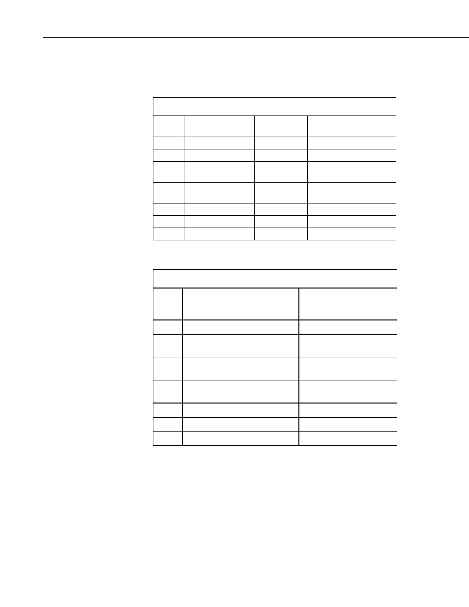
TABLE 7-5. RS-232 Wiring
Color
OBS500 Function
Connection
RS-232 9-pin /
Datalogger Control Port
Red
+12VDC
Power Source
Black Power Ground
Power Ground
White RS-232 Tx (Output) Transmit
Pin 2 Rx (Input)/
Control Port Rx
Blue
RS-232 Rx (Input) Receive
Pin 3 Tx (Output)/
Control Port Tx
Brown
Green
Clear
Shield GND
Ground
7.3.3 Analog 0 to 5 Volt Wiring
TABLE 7-6. Analog 0-5 Volt Wiring
Color
Description
CR800, CR850,
CR1000, CR3000, CR5000,
CR23X, CR10X
Blue
Shutter Open - Control High
Control Port
White Backscatter (Low) or Side Scatter
(High) Control
Control Port
Green Signal
Differential High or Single-
Ended Input
Brown Analog Ground
Differential Low or Analog
Ground
Black Power Ground
G
Red
Power
SW12V
Clear Shield
G
The measurement sequence is to raise the blue wire from ground to 5 volts to
open the shutter, delay 6 seconds, and then measure the backscatter analog
output on the green wire. If side scatter is desired, then raise the white wire
from ground to 5 volts, delay 3 seconds, and then measure the side scatter
analog output on the green wire. In either case, lower the blue wire to ground
to close the shutter. Note that measurements can be differential or single-
ended. Differential measurements are recommended.
The output is scaled as 1 mV per TU. For example, 100 mV = 100 TU, 4000 mV =
4000 TU.
18