1 sdi-12 wiring, Sdi-12 wiring, 3. obs500 connector pin-out – Campbell Scientific OBS500 Smart Turbidity Meter with ClearSensor Technology User Manual
Page 27: 4. sdi-12 wiring
OBS500 Smart Turbidity Meter with ClearSensor™ Technology
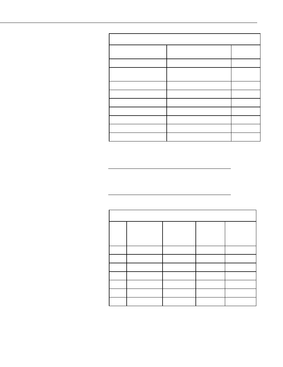
TABLE 7-3. OBS500 Connector Pin-Out
MCIL-8-MP/MCBH-8-FS
Contact Number
Electrical Function
Wire Color
1
Power Ground
Black
2
SDI-12/RS232 TX/Analog SS-
BS Control
White
3
Power (9.6 to 15 V)
Red
4
Analog Signal
Green
5
RS-232 RX/Shutter Open
Blue
6
NC
7
Analog Ground
Brown
8
NC
No Connection
Clear/Braid
This document provides the recommended wiring configuration for connecting
the OBS500 field cable to a Campbell Scientific datalogger. Wiring to
dataloggers or RTUs manufactured by other companies is similar.
Campbell Scientific recommends powering down the system
before wiring the OBS500. The shield wire plays an important
role in noise emissions and susceptibility as well as transient
protection.
7.3.1 SDI-12 Wiring
TABLE 7-4. SDI-12 Wiring
Color
OBS500
Function
CR800,
CR5000,
CR3000,
CR1000
CR200X
Series
CR500,
CR510,
CR23X,
CR10X
Red
+12Vdc
12V
Battery+
12V
Black Power Ground
G
G
G
White SDI-12 Signal
*Control Port C1/SDI-12
Control Port
Brown
Blue
Green
Clear Shield
GND
G
G
*Only odd control ports can be used for SDI-12 (i.e., C1, C3...)
NOTE
17