4 vertical-cavity surface-emitting laser diode, Vertical-cavity surface-emitting laser diode, Scatter detector (acceptance) cones – Campbell Scientific OBS500 Smart Turbidity Meter with ClearSensor Technology User Manual
Page 21
OBS500 Smart Turbidity Meter with ClearSensor™ Technology
The OBS500 has three communication modes: SDI-12, RS-232, or 0 to 5 V.
The mode defaults to SDI-12/RS-232 but can be set in our Device
Configuration Utility to analog. As an SDI-12/RS-232 sensor, the OBS500 is
shipped with an address of 0.
With SDI-12 and RS-232, the basic values output by the OBS500 are
backscatter turbidity, side scatter turbidity, and temperature. The OBS500 can
also output a ratiometric measurement that combines the backscatter and side
scatter measurements. Other diagnostic information is available (see TABLE
7-7) including the raw voltage output from the backscatter and side scatter
sensors, the current to open and close the shutter, an open and close position
count, total open and close cycles, and a moisture alarm. The OBS500 is
shipped from the factory to output turbidity in TU and temperature in degrees
Celsius. The analog output supports backscatter and/or side scatter according
to the status of a control line.
5.4 Vertical-Cavity Surface-Emitting Laser Diode
OBS500 sensors detect suspended matter in water and turbidity from the
relative intensity of light backscattered at angles ranging from 125°
to 170°,
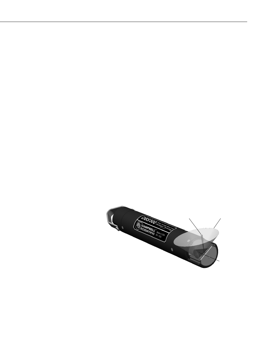
and at 90° for the side scatter measurement. A 3D schematic of the main
components of the sensor is shown in FIGURE 5-2. The OBS500 light source
is a Vertical-Cavity Surface-Emitting Laser diode (VCSEL), which converts
5 mA of electrical current to 2000 μW of optical power. The detectors are low-
drift silicon photodiodes with enhanced NIR responsivity. NIR responsivity is
the ratio of electrical current produced per unit of light power in A/W. A light
baffle prevents direct illumination of the detector by the light source and in-
phase coupling that would otherwise produce large signal biases. A daylight-
rejection filter blocks visible light in the solar spectrum and reduces ambient-
light interference. In addition to the filter, a synchronous detection circuit is
used to eliminate the bias caused by ambient light. The VCSEL is driven by a
temperature-compensated Voltage-Controlled Current Source (VCCS).
FIGURE 5-2. Orientation of emitter cone (source beam) and OBS and
side scatter detector (acceptance) cones
The beam divergence angle of the VCSEL source is 4° worst case and 2°
typical
(95% of the beam power is contained within a 5°
cone).
Emitter Cone
OBS Detector
Cone
90° Side Scatter
Detector Cone
11