Campbell Scientific CS135 Lidar Ceilometer User Manual
Page 34
CS135 Ceilometer
26
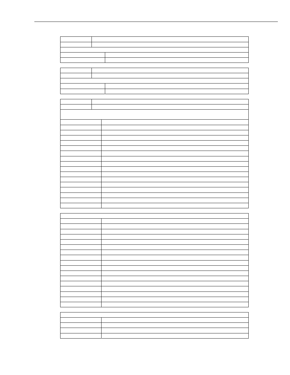
Line
Example line output
15 HOffset
A
Description of the line sections
Section Description
A
Height offset reported in feet or metres dependent upon the UNITS command
Line Example line output
16
LaserRunDays A
Description of the line sections
Section Description
A
Number of days that the laser module has been active for
Line
Example line output
17
Flags 0000 0000 0000
Description of the most significant alarm word (left side, bits going left to right).
Each alarm word is
a hexadecimal sum of all the error bits.
Bit Description
8000 XXXX XXXX
Units. Feet = 0, metre = 1.
4000 XXXX XXXX
Reserved for future use
2000 XXXX XXXX
Reserved for future use
1000 XXXX XXXX
Reserved for future use
0800 XXXX XXXX
Reserved for future use
0400 XXXX XXXX
Laser shut down due to operating temperature out of range
0200 XXXX XXXX
The lead acid battery voltage is reading low
0100 XXXX XXXX
Mains supply has failed (Required a PSU to be present)
0080 XXXX XXXX
The external heater blower assembly temperature is out of bounds
0040 XXXX XXXX
External heater blower failure
0020 XXXX XXXX
The PSUs internal temperature is high
0010 XXXX XXXX
PSU OS has failed its signature check
0008 XXXX XXXX
No communications between DSP and PSU
0004 XXXX XXXX
Photo diode and Laser windows are dirty. This can only be set if the laser is on
0002 XXXX XXXX
Tilt beyond limit set by user, default 45 degrees
0001 XXXX XXXX
No communications between DSP and inclinometer board
Description of the middle alarm word (middle word, bits going left to right)
Bit Description
XXXX 8000 XXXX
The sensors internal humidity is high
XXXX 4000 XXXX
Communications to the DSP boards temperature and humidity chip have failed
XXXX 2000 XXXX
DSP input supply voltage is low
XXXX 1000 XXXX
Self-test active
XXXX 0800 XXXX
Watch dog counter updated
XXXX 0400 XXXX
User setting stored in flash failed their signature checks
XXXX 0200 XXXX
DSP factory calibration stored in flash has failed its signature check
XXXX 0100 XXXX
DSP board OS signature test failed
XXXX 0080 XXXX
DSP board RAM test failed
XXXX 0040 XXXX
DSP boards on board PSUs are out of bounds
XXXX 0020 XXXX
TOP board non-volatile storage is corrupt
XXXX 0010 XXXX
TOP board OS signature test has failed
XXXX 0008 XXXX
TOP boards ADC and DAC are not within specifications
XXXX 0004 XXXX
TOP boards on board PSUs are out of bounds
XXXX 0002 XXXX
Communications have failed between TOP board and the DSP
XXXX 0001 XXXX
Photo diode background radiance is out of range
Description of the least significant alarm word (right side, bits going left to right)
Bit Description
XXXX XXXX 8000
Photo diode temperature is out of range
XXXX XXXX 4000
Photo diode is saturated
XXXX XXXX 2000
Photo diode calibrator temperature is out of range