Horner APG QX651 OCS User Manual
Page 6
MAN0797-03-EN
Specifications / Installation
__________________________________________________________________________________________________________________________________________________
9/16/2009 Page 6 of 7 ECN # 968
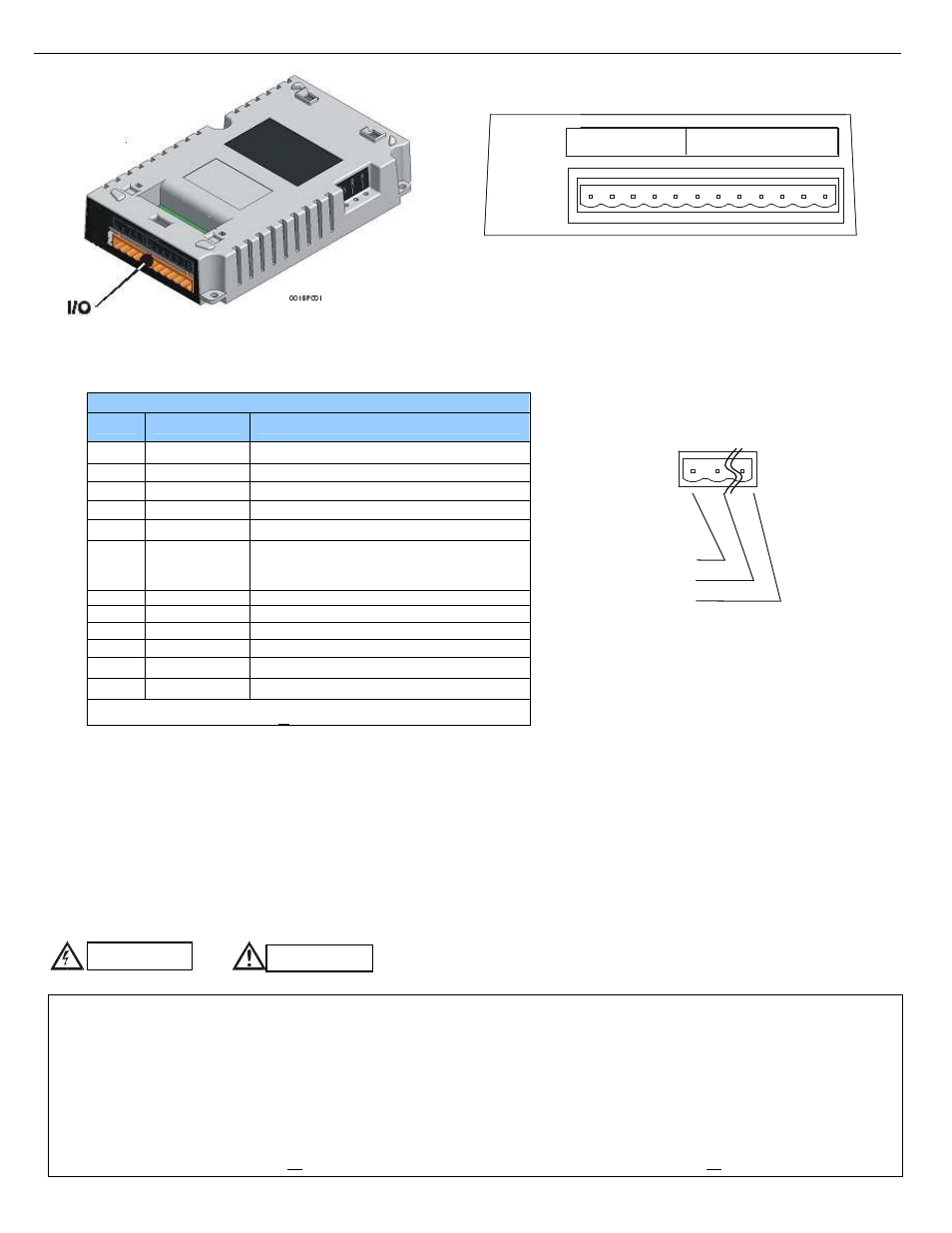
Figure 10 – QX Back Pack Connectors and Ports (Side Views)
Figure 11 – QX Back Pack I/O Port
4
Safety
Table 1 – I/O Port Pins (HSC) (Orange Connector)
Pin
Signal
Description
1
TTL In1
HSC 1 / 5 V Input 1 (See Note*)
2
TTL In2
HSC 2 / 5 V Input 2 (See Note*)
3
TTL In3
HSC 3 / 5 V Input 3 (See Note*)
4
TTL Out1
HSC 1 / 5 V Output 1 (See Note*)
5
TTL Out2
HSC 2 / 5 V Output 2 (See Note*)
6
0 V
Ground
(For best performance, use separate supply and
isolated ground.)
7
In1
HSC 1 / 24 V Input 1 (See Note*)
8
In2
HSC 2 / 24 V Input 2 (See Note*)
9
In3
HSC 3 / 24 V Input 3 (See Note*)
10
Out1
HSC 1/ 24V Output 1 / PWM 1
11
Out2
HSC 2/ 24V Output 2 / PWM 2
12
+24 V
Power for Outputs
Note* - Depending on the output of the application, use
5 V (e.g., TTL In1) or 24 V (e.g., In1) per channel.
001BP003
I/O PORT
O
U
T
2
O
U
T
1
IN
3
IN
2
IN
1
O
U
T
2
O
U
T
1
TTL
IN
3
IN
2
IN
1
E
X
T
0
V
E
X
T
+
2
4
V
Close-up of the Back Pack I/O Connector
PI
PI2
P 12
This equipment is suitable for use in Class I, Division 2, Groups A, B, C and D or Non-hazardous locations only
WARNING – EXPLOSION HAZARD – Do not disconnect equipment unless power has been switched off or the area is known to be non-hazardous.
AVERTISSEMENT - RISQUE D'EXPLOSION - AVANT DE DECONNECTOR L'EQUIPMENT, COUPER LE COURANT OU S'ASSURER QUE L'EMPLACEMENT EST
DESIGNE NON DANGEREUX.
WARNING: To avoid the risk of electric shock or burns, always connect the safety (or earth) ground before making any other connections.
WARNING: To reduce the risk of fire, electrical shock, or physical injury it is strongly recommended to fuse the voltage measurement inputs. Be sure to locate fuses as close
to the source as possible.
WARNING: Replace fuse with the same type and rating to provide protection against risk of fire and shock hazards.
WARNING: In the event of repeated failure, do not replace the fuse again as a repeated failure indicates a defective condition that will not clear by replacing the fuse.
3.5
CAN Network Port and Wiring (QX Base and QX Back Pack)
See the latest edition of Horner’s CAN Networks Manual (MAN0799) by referring to the website location listed in the Technical Support section in this document.
Note: To optimize CAN network reliability in electrically noisy environments, the V- CAN Ground needs to be isolated from the primary input power supply ground.
Warning: Consult
user documentation.
Warning: Electric
Shock hazard
When found on the product, the following symbols specify: