Horner APG XL7 OCS User Manual
Page 5
Specifications/Installation
MAN0971-02-EN
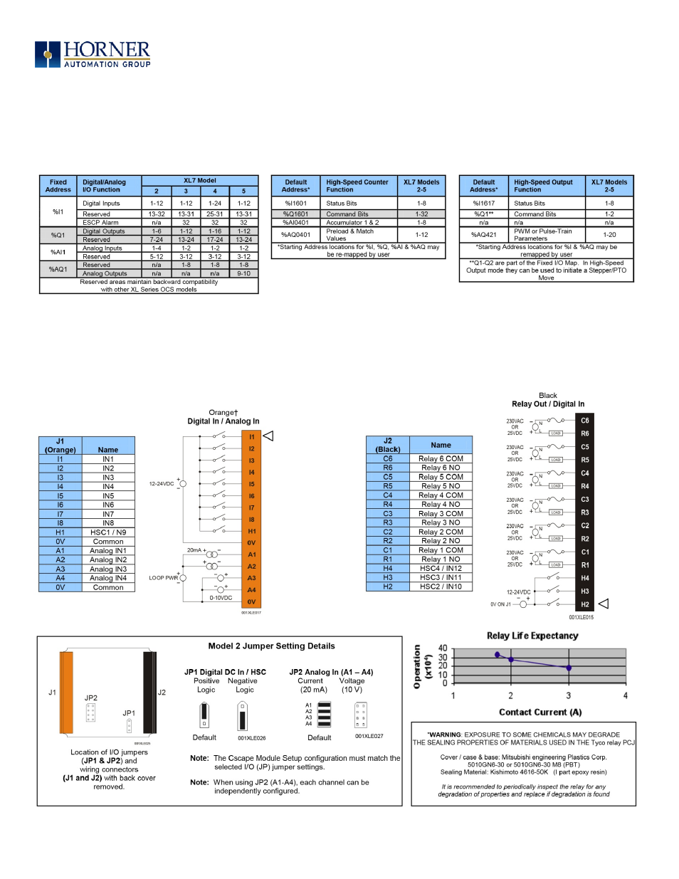
8. Built-in I/O (Model 2, 3, 4 & 5)
All XL7 models (except the HE-XW1E0) feature built-in I/O. The I/O is mapped into OCS Register space, in three separate areas –
Digital/Analog I/O, High-Speed Counter I/O, and High-speed Output I/O. Digital/Analog I/O location is fixed starting at 1, but the High-
speed Counter and High-speed Output references may be mapped to any open register location. For more details on using the High-
Speed Counter and High-Speed Outputs, see the XL7 OCS User’s Manual (MAN0974-01).
Model 2 – I/O
The XL7 model 2 (HE-XW1E2) features 12 DC Inputs, 6 Relay outputs, and 4 Analog Inputs. The DC Inputs are 12/24Vdc compatible, and
can be jumpered for Positive Logic (sinking), or Negative Logic (sourcing). Two of the inputs (H1-H2) can be used for high-speed functions
up to 500kHz. The 12-bit Analog Inputs can be jumpered for voltage (0-10V) or current (4-20mA) on a channel by channel basis. The
Relay outputs are isolated, supporting AC and DC voltages, with output currents of up to 3A/relay, 5A total.
Page 5 of 7