Horner APG XLt OCS HEXT240C015 User Manual
Page 3
MAN0873-06-EN
Specifications / Installation
________________________________________________________________
___________________________________________________________________
12/18/2008
Page 3 of 4 ECN # 947
_______________________________
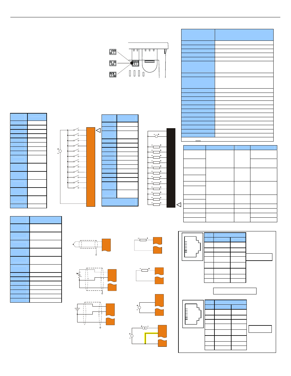
4.2
External DIP Switch Settings (or Jumpers Settings)
4.3 Wiring
Examples
Note: The wiring examples show Positive Logic input wiring.
J1
Orange
Name
I1 IN1
I2 IN2
I3 IN3
I4 IN4
I5 IN5
I6 IN6
I7 IN7
I8 IN8
H1
HSC1 /
IN9
H2
HSC2 /
IN10
H3
HSC3 /
IN11
H4
HSC4 /
IN12
NC
No
Connect
NC
No
Connect
0V Ground
J3
Orange
Name
T1+
T/C / RTD IN1+ /
100 mV+
T1-
T/C / RTD IN1- /
100 mV-
T2+
T/C / RTD IN2+ /
100 mV+
T2-
T/C / RTD IN2- /
100 mV-
AQ1
10 V / 20 mA
OUT1
AQ2
0 V / 20 mA
OUT2
0V Ground
MA1 20
mA
IN1
V1
10 V IN1
0V Ground
MA2 20
mA
IN2
V2
10 V IN2
0V Ground
5 I/O
Register
Map
Registers
Description
%I1 to %I24
Digital Inputs
%I32 Output
Fault
%I25 to %I31
Reserved
%Q1 to %Q16
Digital outputs
%Q17
Clear HSC1 accumulator to 0
%Q18
Totalizer: Clear HSC2
Quadrature 1-2: Accumulator 1
Reset to max – 1
%Q19
Clear HSC3 Accumulator to 0
%Q20
Totalizer: Clear HSC4
Quadrature 3-4: Accumulator 3
Reset to max – 1
%Q21 to %Q32
Reserved
%AI1 to %AI4
Analog inputs
%AI5, %AI6
HSC1 Accumulator
%AI7, %AI8
HSC2 Accumulator
%AI9, %AI10
HSC3 Accumulator
%AI11, %AI12
HSC4 Accumulator
%AQ1, %AQ2
PWM1 Duty Cycle
%AQ3, %AQ4
PWM2 Duty Cycle
%AQ5, %AQ6
PWM Prescale
%AQ7, %AQ8
PWM Period
%AQ9 to %AQ14
Analog outputs
Note: Not all XLe units contain the I/O listed in this table.
Registers
PWM
HSC
Stepper
%AQ1
Start
Frequency
%AQ2
PWM1 Duty
Cycle
(32 bit)
HSC1
Preset
Value
Run
Frequency
%AQ3
%AQ4
PWM2 Duty
Cycle
(32 bit)
HSC2
Preset
Value
Accel Count
(32 bit)
%AQ5
%AQ6
PWM
Prescale
(32 bit)
Run Count
(32 bit)
%AQ7
%AQ8
PWM Period
(32 bit)
Decel Count
(32 bit)
%Q1
Run
%I30 Ready/Done
%I31
Error
6
MJ2 Pinouts in Full and Half Duplex Modes
J2
Black
Name
0V Ground
V+* V+*
NC
No
Connect
Q12 OUT12
Q11 OUT11
Q10 OUT10
Q9 OUT9
Q8 OUT8
Q7 OUT7
Q6 OUT6
Q5 OUT5
Q4 OUT4
Q3 OUT3
Q2
OUT2 /
PWM2
Q1
OUT1 /
PWM1
V+* Supply for
Sourcing Outputs
I1
I2
I3
I4
H2
H3
H4
0V
I5
I6
I7
I8
NC
NC
H1
001XLE007
12-24
VDC
J1 Orange
Positive Logic
Digital In
Q1
Q2
Q3
Q4
Q9
Q10
Q11
Q12
Q5
Q6
Q7
Q8
V+
0V
LOAD
LOAD
LOAD
LOAD
LOAD
LOAD
LOAD
LOAD
LOAD
LOAD
LOAD
LOAD
10 - 30VDC
NC
001XLE008
J2 Black
Positive Logic
Digital Outputs
J3 Orange
Analog In / Analog Out
Note: A total of 2 Analog Inputs can be used (T/C, RTD, mV, mA, and V).
0 -10 V Analog Out
AQ1
0V
10VDC
4 - 20 mA Analog Out
AQ1
0V
20mA
Thermocouple In
T1+
T1-
The External DIP Switches are used
for termination of the RS-485 ports.
The XLt is shipped un-terminated.
To terminate, select one of the
jumpers shipped with the product and
insert it based upon the option that is
desired or, select the switch and
configure based upon the option that
is desired.
As seen when looking at the top of the XLt unit: Refer to
Section 3 for the location of the External Jumpers.
0 – 10 V Analog In
0-10VDC
MA1
V1
0V
NC
RTD In
T1+
T1-
0V
mV In
T1+
T1-
0V
100mV+
100mV-
Note: Be sure to
wire 0 V to V1 as
shown for proper
operation.
Note: Loop Power (LOOP
PWR) requirements are
determined by the transmitter
specification.
LOOP PWR
20mA
MA1
V1
0V
20 mA Analog In
001XLE037-R1
DIPSW3: FACTORY USE
ONLY (tiny bootloader firmware
downloading). NOT TO BE
USED FOR NORMAL OCS
OPERATION.
DIPSW2: MJ2 Termination
(default – none)
DIPSW1: MJ1 Termination
(default – none)
Full Duplex
Half Duplex
Pin
MJ2 Pins
Signal
Direction
8
TXD OUT
7
RXD IN
6
0 V
Ground
5*
+5 60mA
OUT
4
TX- OUT
3
TX+ OUT
2
RX- IN
1
RX+ IN
1
8
* +5Vdc 60mA Max
Pin
MJ2 Pins
Signal
Direction
8
TXD OUT
7
RXD IN
6
0 V
Ground
5*
+5 60mA
OUT
4
TX- OUT
3
TX+ OUT
2
TX-/RX- IN/OUT
1
TX+/RX+ IN/OUT
1
8