Horner APG XLt OCS HEXT240C100 User Manual
Page 2
MAN0868-04-EN
Specifications / Installation
__________________________________________________________________________________________________________________________________________________________________
12/19/2008
Page 2 of 3 ECN # 947
5
Wiring and Jumpers
Wire according to the type of inputs / outputs used, and select the
appropriate jumper option.
•
Use Only Copper Conductors in Field Wiring, 60/75° C
5.1
External DIP Switch Settings
6
MJ2 Pinouts in Half and Full Duplex Modes
Wiring Specifications
For CAN wiring, use the
following wire type or equivalent:
Belden 3084, 24 AWG (0.2 mm
2
)
or larger.
4
Serial Communications:
MJ1: (RS-232 / RS-485) Use for Cscape programming and
Application-Defined Communications.
MJ2: (RS-232 / RS-485) Use for Application-Defined
Communications.
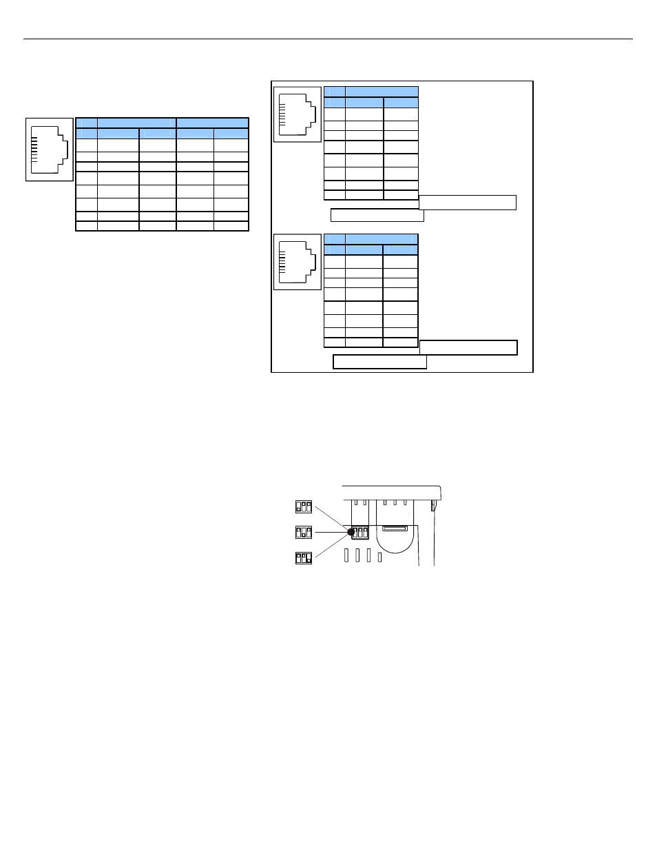
As seen when looking at the top of the XLt unit:
DIPSW3: FACTORY USE ONLY (tiny
bootloader firmware downloading). NOT
TO BE USED FOR NORMAL OCS
OPERATION.
DIPSW2: MJ2 Termination
(Default – none)
DIPSW1: MJ1 Termination
(Default – none)
001XLE037-R1
The DIP Switches are used for
termination of the RS-485 ports. The
XLt is shipped un-terminated.
To terminate, select one of the DIP
Switches and configure it based upon
the option that is desired.
Pin
MJ1 Pins
MJ2 Pins
Signal
Direction
Signal
Direction
8
TXD OUT TXD OUT
7
RXD IN RXD
IN
6
0 V
Ground
0 V
Ground
5*
+5 60mA
OUT
+5 60mA
OUT
4
RTS OUT TX- OUT
3
CTS IN TX+
OUT
2
RX- / TX-
IN / OUT
RX-
IN
1
RX+ / TX+
IN / OUT
RX+
IN
1
8
* +5Vdc 60mA Max
MJ2 Half Duplex Mode
Pin
MJ2 Pins
Signal
Direction
8
TXD OUT
7
RXD IN
6
0 V
Ground
5*
+5 60mA
OUT
4
TX- OUT
3
TX+ OUT
2
TX-/RX- IN/OUT
1
TX+/RX+ IN/OUT
1
8
Pin
MJ2 Pins
Signal
Direction
8
TXD OUT
7
RXD IN
6
0 V
Ground
5*
+5 60mA
OUT
4
TX- OUT
3
TX+ OUT
2
RX- IN
1
RX+ IN
1
8
MJ2 Full Duplex Mode
* +5Vdc 60mA Max