Horner APG XLe OCS HEXE220C012 User Manual
Page 2
MAN0808-09-EN
Specifications / Installation
__________________________________________________________________________________________________________________________________________________________________
12/18/2008
Page 2 of 4 ECN # 947
5
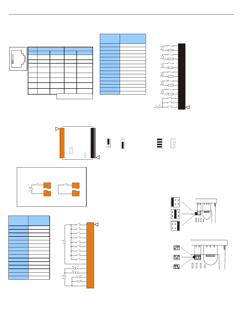
Wiring and Jumpers
Wire according to the type of inputs / outputs used, and select the
appropriate jumper option.
5.1
Wiring Examples
J1 Orange
Terminal
Connector
Name
I1 IN1
I2 IN2
I3 IN3
I4 IN4
I5 IN5
I6 IN6
I7 IN7
I8 IN8
H1 HSC1
/IN9
0V Ground
A1 Analog
IN1
A2 Analog
IN2
A3 Analog
IN3
A4 Analog
IN4
0V Ground
5.2
Wiring Examples (continued)
J2 Black
Terminal
Connector
Name
C6
Relay 6 COM
R6
Relay 6 NO
C5
Relay 5 COM
R5
Relay 5 NO
C4
Relay 4 COM
R4
Relay 4 NO
C3
Relay 3 COM
R3
Relay 3 NO
C2
Relay 2 COM
R2
Relay 2 NO
C1
Relay 1 COM
R1
Relay 1 NO
H4
HSC4 / IN12
H3
HSC3 / IN11
H2
HSC2 / IN10
5.3
I/O Jumpers Settings (JP1 - JP2)
5.4
External DIP Switch Settings (or Jumpers Settings)
Note: The Cscape Module Setup configuration must match the
selected I/O (JP) jumper settings.
001XLE026
gital DC In / HSC
Positive Negative
Logic Logic
Default
001XLE027
A1
A2
A3
A4
JP1 Di
JP2 Analog In (A1 – A4)
Current Voltage
(20 mA) (10 V)
Default
J1
JP2
JP1
J2
001XLE025
Location of I/O jumpers (JP)
and wiring connectors
(J1 and J2).
I1
0V
001XLE036
12-24VDC
I1
0V
Positive Logic In Negative Logic In
Positive Logic vs. Negative Logic Wiring
The XLe can be wired for Positive Logic inputs or
Negative Logic inputs.
001XLE015
0V ON J1
12-24VDC
R2
C2
R3
C3
R6
C6
R4
C4
R5
C5
R1
C1
H4
H2
H3
LOAD
230VAC
OR
25VDC
N
L
LOAD
230VAC
OR
25VDC
N
L
LOAD
230VAC
OR
25VDC
N
L
LOAD
230VAC
OR
25VDC
N
L
LOAD
230VAC
OR
25VDC
N
L
LOAD
230VAC
OR
25VDC
N
L
J2 Black
Positive Logic
Digital In / Relay Out
Wiring Specifications
For I/O wiring (discrete), use the
following wire type or equivalent:
Belden 9918, 18 AWG (0.8 mm
2
)
or larger.
For shielded Analog I/O wiring,
use the following wire type or
equivalent: Belden 8441, 18
AWG (0.8 mm
2
) or larger.
For CAN wiring, use the
following wire type or equivalent:
Belden 3084, 24 AWG (0.2 mm
2
)
or larger.
Use copper conductors in field
i i
l
60/75° C
Some XLes have jumpers to set
RS-485 port termination, though
most use DIP Switches.
The External Jumpers or DIP
Switches are used for termination
of the RS-485 ports. The XLe is
shipped un-terminated.
To terminate, select one of the
jumpers shipped with the product
and insert it based upon the option
that is desired or, select the switch
and configure based upon the
option that is desired.
DIPSW3: FACTORY
USE ONLY (tiny
bootloader firmware
downloading). NOT TO
BE USED FOR
NORMAL OCS
OPERATION.
DIPSW2: MJ2
Termination
(Default – none)
DIPSW1: MJ1
Termination
(Default – none)
001XLE037
As seen when looking at the top of the XLE unit: Refer to
Section 3 for the location of the DIP Switches (or External
Jumpers).
XE102 J1 Orange
Positive Logic In
Digital In /
Analog In
I1
I2
I3
I4
0V
A1
A2
0V
I5
I6
I7
I8
A3
A4
H1
001XLE017
12-24VDC
LOOP PWR
20mA
0-10VDC
Note:
When using JP2 (A1-A4), e
ach
channel can be independently
configured.
Note:
Loop Power requirements are determined
by the transmitter specification.
Pin
MJ1 Pins
MJ2 Pins
Signal
Direction
Signal
Direction
8
TXD OUT TXD OUT
7
RXD IN RXD IN
6
0 V
Ground
0 V
Ground
5*
+5
60mA
OUT
+5
60mA
OUT
4
RTS OUT TX- OUT
3
CTS IN TX+ OUT
2
RX- /
TX-
IN / OUT
RX-
IN
1
RX+ /
TX+
IN / OUT
RX+
IN
1
8
4
Serial Communications:
MJ1: (RS-232 / RS-485) Use for Cscape programming and
Application-Defined Communications.
MJ2: (RS-232 / RS-485) Use for Application-Defined
Communications.
DIPSW3: FACTORY
USE ONLY (tiny
bootloader firmware
downloading). NOT TO
BE USED FOR
NORMAL OCS
OPERATION.
DIPSW2: MJ2
Termination
(Default – none)
DIPSW1: MJ1
Termination
(Default – none)
001XLE037-R1
* +5 on XLe Rev E and later