Red Lion GEMINI 52 User Manual
Description, Specifications, Dimensions in inches (mm)
1
!
DIFFERENCE (A-B), OR DRAW [(A-B)/B] INDICATION
!
6-DIGIT, 0.56" (14.2 mm) HIGH LED DISPLAY WITH NEGATIVE
SIGN, OVERFLOW & DISPLAYED VALUE INDICATORS
!
THREE SEPARATELY DISPLAYABLE VALUES: A, B, & C
!
TWO PRESETS ASSIGNABLE TO A, B, OR C
!
SEPARATE INPUT SCALING FOR BOTH RATE A & B CHANNELS
!
ACCEPTS COUNT RATES TO 10 KHz
!
SOLID-STATE CURRENT SINK OUTPUTS
!
OPTIONAL 20 mA CURRENT LOOP FOR SERIAL DATA
COMMUNICATION
!
OPTIONAL RELAY OUTPUTS (Field Replaceable)
!
PROGRAMMABILITY OF DECIMAL POINT LOCATION & LEADING
ZERO BLANKING
!
PROGRAMMABLE TIMED OUTPUTS (0.01 TO 599.99 sec.)
!
ABILITY TO LOCK OUT FRONT PANEL FUNCTIONS
!
SEALED FRONT PANEL CONSTRUCTION (NEMA 4/IP65)
!
NON-VOLATILE MEMORY (E
2
PROM)
DESCRIPTION
The Gemini 5200 is a multifunction dual rate indicator which can fulfill
almost any rate indication application. The unit can operate as two independent
rate indicators, with scaling, decimal point placement, and update times
separately programmable for each channel. The Gemini 5200 also has three other
unit personalities. These personalities feature a third display Channel C, which
can indicate the ratio, difference or draw between the A and B rate channels.
The programming of the rate channels and the calculated display is a very
straightforward task. Setting up Channel C only requires programming the
desired amount of resolution (for ratio and draw) and the appropriate decimal
point location. The Gemini 5200 simply takes the two rate values and
mathematically calculates display “C” accordingly.
The rate indicators use a time interval method (1/tau) to calculate the rate
value. This method enables high resolution at all input rates. The unit counts
input pulses and after a programmable minimum update time has occurred, it
waits until the next count edge occurs, then takes the elapsed time and number
of edges and calculates the rate value. At slower rates, averaging can be
accomplished by programming the “Rate Minimum Update Time” (0.5 sec. to
16 sec.) for the desired response. The minimum input frequency is 0.03
counts/sec. or one pulse every 32 sec. Extensive scaling capabilities allow
practically any desired reading at very slow input rates.
The 20 mA Current Loop Communications Option provides the capability of
two-way serial communications between the Gemini and other equipment such
as a printer, programmable controller, or host computer. The baud rate can be
set to 300, 600, 1200, or 2400 baud. The format for transmitted and received
data is 1 start bit, 7 data bits, 1 parity bit (odd), and a stop bit. When utilizing
an external power supply (30 VDC max.), up to sixteen units can be installed in
the loop, each with an individual address. When utilizing the Gemini’s 20 mA
current source, up to seven units can be installed in a loop. The Rate values,
Presets, and Scale Factors can all be interrogated, while the Presets and Scale
Factors can also be changed by sending the proper command codes and
numerical data. Various “Print Options” can be selected to automatically
interrogate the Rate values, Presets, or Scale Factors by activating the “Print
Request” terminal when a printer is being used.
The construction of the Gemini 5200 features a metal die-cast bezel, offering
maximum durability with a high quality appearance. The sealed front panel
meets NEMA 4/IP65 specifications for wash-down and/or dust when properly
installed. Electrical connections are made via plug-in terminal strips. Clamp-
type pressure plate terminals accept stripped #14 AWG wire without lugs.
SPECIFICATIONS
1. DISPLAY: 6-digit 0.56" (14.2 mm) High LED display.
2. POWER REQUIREMENTS:
AC Power: Switch selectable 115/230 VAC (±10%), 50/60 Hz, 20 VA
DC Power: 11 to 14 VDC @ 0.7 A max.
3. SENSOR POWER: +12 VDC (±25%) @ 100 mA.
4. MEMORY: Non-volatile E
2
PROM memory retains all programming
information when power is removed or interrupted.
Power Cycles (ON/OFF): 100,000 min.
Data Retention: 10 years min.
5. INPUTS A AND B: Switch selectable to accept pulses from a variety of
sources including switch contacts, outputs from CMOS or TTL circuits, and
all standard RLC sensors.
Current Sourcing: Unit provides 3.9 K
Ω
pull-down resistor for sensors with
current sourcing outputs. (Max. input voltage = 28 VDC @ 7 mA.)
Current Sinking: Unit provides 7.8 K
Ω
pull-up resistor for sensors with
current sinking outputs. (Max. sensor current = 1.6 mA.)
Debounce: Damping capacitor provided for switch contact debounce. Limits
rate to 100 Hz max. with 50% duty cycle.
Lo Bias: Input trigger levels V
IL
= 1.5 V, V
IH
= 3.75 V
Hi Bias: Input trigger levels V
IL
= 5.5 V, V
IH
= 7.5 V
Note: Bias levels given are ±10% @ 12 VDC. They vary proportionally with
sensor supply voltage at “DC OUT” terminal.
6. MAGNETIC PICKUP INPUTS A & B:
Sensitivity: 150 mV peak (typical @ 12 VDC)
Hysteresis: 100 mV
Input Impedance: 26.5 K
Ω
@ 60 Hz
Maximum Input Voltage: ±50 Vp
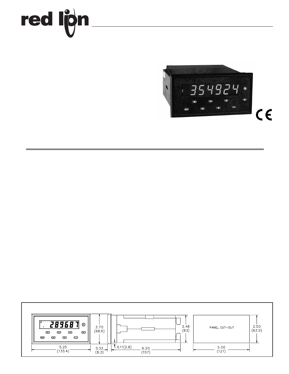
GEMINI 5200 - PRESETTABLE DUAL RATE INDICATOR WITH RATIO (A/B)
DIMENSIONS In inches (mm)
Note: Recommended minimum clearance (behind the panel) for mounting clip installation is 6.8" (173) W.
Bulletin No. GEM5-C
Drawing No. LP0321
Released 1/05
Tel +1 (717) 767-6511
Fax +1 (717) 764-0839
www.redlion.net