Alibrating, Eter – Red Lion PAXLRT User Manual
Page 7
7
To enter Calibration Mode, select
< >
at the end
of Programming Mode, and press the PAR key. In Calibration Mode, the user
can restore the meter to factory default settings or recalibrate the signal input if
necessary.
To prevent inadvertent entries, an access code must be entered to perform any
operation in Calibration Mode. Upon entering Calibration Mode, the meter
initially displays Code 50. Press the up or down arrow keys to select the access
code for the desired operation. If an access code other than those shown below
is entered, the meter exits Calibration Mode and returns to normal display mode.
The factory settings for the programming parameters are shown in the
previous section in the alternating display illustrations. All programming
parameters can be restored to the factory default settings by entering the access
Code 66 and pressing the PAR key. The meter briefly displays
and then
returns to Code 50. This procedure resets only parameters that are accessed
through Programming Mode. The Calibration Mode settings (input calibration
levels) are not affected.
The meter has been fully calibrated at the factory. If the meter appears to be
indicating incorrectly or inaccurately, refer to the troubleshooting section
before attempting this procedure. When re-calibration is required (generally
every 2 years), the procedure should only be performed by qualified
technicians using appropriate equipment. Resistance source accuracies of
0.02% or better are required.
The procedure consists of applying accurate signal levels to the meter input
in a series of two steps. Allow a 30-minute warm-up period before starting
calibration. To begin the input calibration, enter access Code 48 and press the
PAR key.
ENTER ZERO REFERENCE
Meter displays
. Apply 0 ohms to the meter input by shorting Terminals 4,
5, and 6. Allow the meter to stabilize at least 20 seconds after shorting the
terminals, and then press PAR.
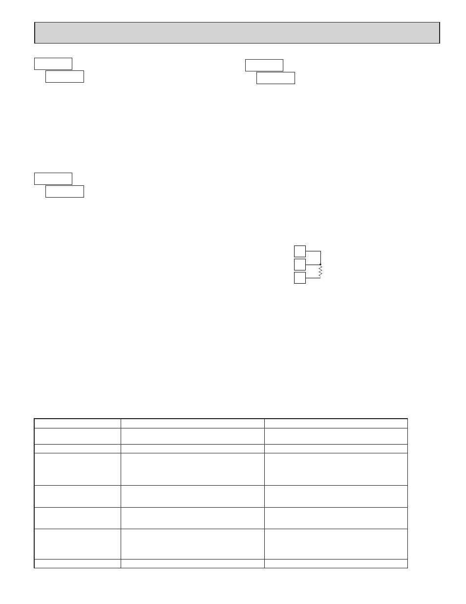
APPLY PRECISION RESISTANCE
Meter displays
. Connect a precision 300 ohm resistor across Terminals
5 and 6. Terminals 4 and 5 remain shorted. (Note: Be certain to short Terminals
4 and 5 at the resistor as shown in the drawing below. Shorting terminals may
lead to incorrect calibration.)
Allow the meter to stabilize at least 20 seconds after making the connections,
and then press PAR. The meter briefly displays
and returns to the normal
display mode. Calibration is now complete. It is recommended to check
calibration by comparing the displayed temperature with a precision thermometer.
to
TROUBLESHOOTING
The majority of all problems with the meter can be traced to improper connections or improper programming set-ups. Be sure all connections are
clean and tight and check the programming set-ups for correct data.
For further technical assistance, contact technical support at the appropriate company numbers listed.
CALIBRATION MODE
FACTORY SETTINGS
METER INPUT CALIBRATION
6
5
4
300
Ω
5.0 C
ALIBRATING
THE
M
ETER
PROBLEM
POSSIBLE CAUSE
REMEDIES
NO DISPLAY
1. Power off, improperly connected, or brown-out.
“
” IN DISPLAY
1. Program data error.
1. Press PAR and check data set-ups.
“
” or “
” IN DISPLAY
1. Input display out of range.
2. Loss of data set-ups.
DISPLAY WANDERS
1. Loss of data set-ups.
1. Electrical “Noise” in process or sensor lines.
2. Process inherently unstable.
“
” IN DISPLAY
1. Connect probe.
2. Repair or obtain new probe.
3. Reduce temperature.
4. Check input levels.
“
” IN DISPLAY
1. Input shorted.
1. Check input connections.
1a. Check data set-ups.
1b. Disconnect and reconnect power.
1c. Check for electrical disturbance.
1a. Check wiring.
1b. Verify power.
1a. Change display resolution to “1” degree.
1b. Reduce offset value.
2a. Check data set-ups.
2b. Check for electrical disturbance.
2c. Disconnect and reconnect power.
1a. Increase digital filtering.
1b. Re-route signal wires.
2. Dampen process to eliminate oscillations.
1. Probe unconnencted.
2. Broken or burnout probe.
3. Excessive probe temperature.
4. Input overload.
JITTERY DISPLAY