Roubleshooting, Alibration, Paxli – Red Lion PAXLVD User Manual
Page 7: Direct current meter readout, Scaling current meter readout, Block diagram paxli, Input calibration
7
DIRECT CURRENT METER READOUT
When the application requires direct current meter readout, the Scale Switch
should remain in the “OFF” position. The Input Range Jumper is set to the
current range being applied. It is possible to select a range higher than being
applied to get lower resolution. The Decimal Point switches are set to resolution
of the selected Input Range Jumper.
SCALING CURRENT METER READOUT
In many industrial applications, a current meter is required to display a
reading in terms of PSI, RPM, or some other unit of measure. The signal voltage
being measured can be generated by a transducer that senses the variations and
delivers a linear output voltage. To provide the desired readout at the specified
current, the current meter must be scaled.
Place the Scale Switch in the “ON” position. This enables the Scale
Potentiometer which is accessible from the back of the meter. (Enabling the
Scale Potentiometer does NOT affect the calibration of the meter.) Place the
Decimal Point Switches to the proper location. The Input Range Jumper is set
to the current range being applied. Apply the meter power and the current signal.
Adjust the Scale Potentiometer to the desired value. Scaling to obtain a
numerical readout higher than the normal value of the current can also be
accomplished, in most cases, by selecting a lower current range. However, the
maximum current for the range must not be exceeded. (See Specifications for
maximum input currents.)
This scaling only effects the span. There is no offset scaling. This means that
only zero amps can display a value of zero.
EXAMPLE: The Pax Current Meter has been connected to measure a circuit
current to 120.0 mA maximum. However, in this application, the display is to
indicate percent of load current with 120.0 mA equivalent to 100.0 percent.
The scale potentiometer is adjusted to reduce the normal 120.0 mA signal
input display reading of 120.0 to indicate the desired reading of 100.0 on the
display. Scaling to obtain a numerical readout higher than the normal value
of the current can also be accomplished in most cases by selecting a lower
current range. However, the maximum current for the range must not be
exceeded. (See Specifications for maximum input currents.)
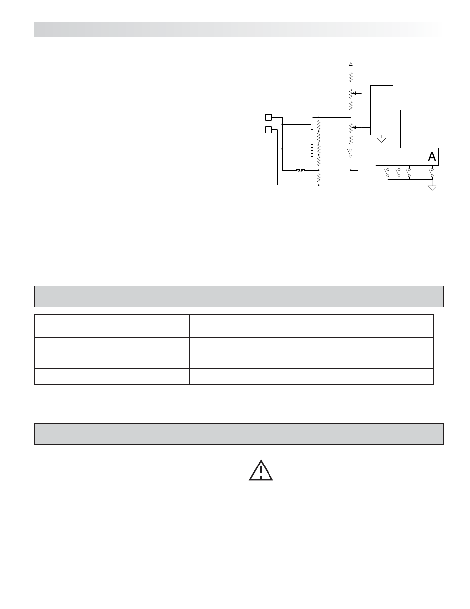
PROCESS
CIRCUITRY
+VDC
S3
S2
S1
S4
COMMON
+SIGNAL
0-199.9mA
0-19.99mA
1
Ω
9
Ω
S5
0-1.999mA
0-199.9
µA/
90
Ω
900
Ω
POT
SCALE
.1
Ω
0-1.999A
1.9.9.9
199.9mV
BLOCK DIAGRAM PAXLI
PROBLEM
REMEDIES
NO DISPLAY
CHECK
: Power switch and line voltage
INCORRECT DISPLAY
OVER-RANGE INDICATION
CHECK
: Input jumper position
VERIFY
: Input signal
CHECK
: Input jumper position
CHECK
: Scaling adjustment pot DIP switch position
ADJUST
: Scaling pot
VERIFY
: Input Signal
For further assistance, contact technical support at the appropriate company numbers listed.
PAXLI
5.0 T
ROUBLESHOOTING
6.0 C
ALIBRATION
The meter has been fully calibrated at the factory. Scaling to convert the input
signal to a desired display value is performed by enabling the scale pot DIP
switch. If the meter appears to be indicating incorrectly or inaccurately, refer to
Troubleshooting before attempting to calibrate the meter.
When recalibration is required (generally every 2 years), it should only be
performed by qualified technicians using appropriate equipment.
Input Calibration
WARNING: Calibration of this meter requires a signal source
with an accuracy of 0.01% or better and an external meter with an
accuracy of 0.005% or better.
Before starting, verify that the Input Range Jumper is set for the range to be
calibrated. Also verify that the precision signal source is connected and ready.
Allow a 30 minute warm-up period before calibrating the meter.
Then perform the following procedure:
1. Place jumper in 2 V range (PAXLV) or 2 mA range (PAXLI).
2. Set the DIP switch off to disable the scaling pot.
3. Apply half scale input signal.
4. Adjust calibration potentiometer as necessary for the display to read 1000
(ignore decimal point).
5. Apply zero signal and ensure display reads zero.
6. Apply full scale signal and ensure display reads 1999.
Note: Any individual range may be recalibrated (scaled) to 0.1% accuracy with
appropriate calibration equipment.