Etting, Umpers, Witches – Red Lion PAXLVD User Manual
Page 4: Nstalling, Eter, Paxli jumper selection, Installation, Installation environment
The meter has an input jumper and switches, which must be checked and/or
changed prior to applying power. To access the input jumper and switches,
remove the meter base from the case by firmly squeezing and pulling back on
the side rear finger tabs. This should lower the latch below the case slot (which
is located just in front of the finger tabs). It is recommended to release the latch
on one side, then start the other side latch.
Power Selection Switch
Caution: Insure the AC power selection switch is set for the
proper voltage before powering the meter. The meter is shipped
from the factory in the 230 VAC position.
Input Range Jumper
A jumper is used for selection of the voltage or current input range. Select the
proper input range that will be high enough to avoid input signal overload. It is
important that only one jumper position is used at a time. Avoid placing a jumper
across two different input ranges.
Set-Up DIP Switches
A DIP switch is located inside the meter. It is used for the selection of decimal
points, backlight annunciator, and scaling. Selecting the “ON” position enables
the function.
PAXLI Jumper Selection
ONLY ONE
THIS AREA!
JUMPER IN
CURRENT
REAR TERMINALS
±1.999A
/199.9mV
±199.9µA
±199.9mA
±19.99mA
±1.999mA
INPUT RANGE JUMPER
JUMPER SELECTIONS
The
indicates factory setting.
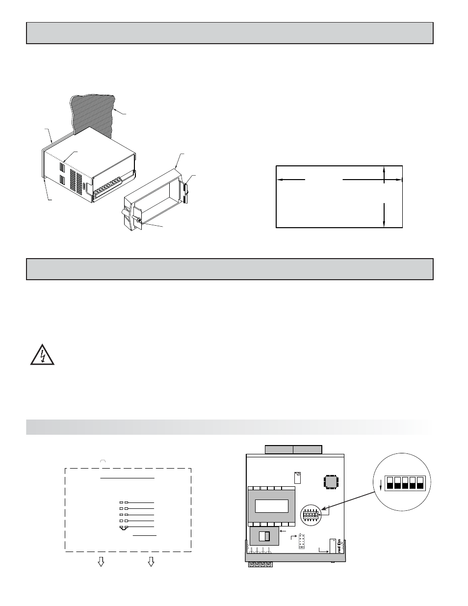
Main
Circuit
Board
SET-UP
DIP
SWITCHES
POWER SELECTION SWITCH
INPUT
RANGE
JUMPER
SCALING
POT
230
11
5
REAR TERMINALS
FRONT DISPLAY
4
2.0 S
ETTING
THE
J
UMPERS
AND
S
WITCHES
SWITCH
FUNCTION
1
Decimal Point 1 (000.0)
2
Decimal Point 2 (00.00)
3
Decimal Point 3 (0.000)
4
Backlight Annunciator for Units Label
5
Enables the Scaling Pot
1.0 I
NSTALLING
THE
M
ETER
Installation
The PAX meets NEMA 4X/IP65 requirements when properly installed. The
unit is intended to be mounted into an enclosed panel. Prepare the panel cutout
to the dimensions shown. Remove the panel latch from the unit. Slide the panel
gasket over the rear of the unit to the back of the bezel. The unit should be
installed fully assembled. Insert the unit into the panel cutout.
While holding the unit in place, push the panel latch over the rear of the unit
so that the tabs of the panel latch engage in the slots on the case. The panel latch
should be engaged in the farthest forward slot possible. To achieve a proper seal,
tighten the latch screws evenly until the unit is snug in the panel (Torque to
approximately 7 in-lbs [79N-cm]). Do not over-tighten the screws.
Installation Environment
The unit should be installed in a location that does not exceed the maximum
operating temperature and provides good air circulation. Placing the unit near
devices that generate excessive heat should be avoided.
The bezel should be cleaned only with a soft cloth and neutral soap product.
Do NOT use solvents. Continuous exposure to direct sunlight may accelerate the
aging process of the bezel.
-.00
(92 )
-.0
+.8
3.62
+.03
(45 )
1.77
-.0
+.5
-.00
+.02
PANEL CUT-OUT
LATCHING
TABS
PANEL
LATCH
PANEL
MOUNTING
SCREWS
LATCHING
SLOTS
PANEL
GASKET
BEZEL
PANEL
3
5
4
1
2
ON