Caling, Eter, 1 power wiring – Red Lion PAXLVD User Manual
Page 6: 2 input signal wiring, Paxlv
4.0 S
CALING
THE
M
ETER
3.1 POWER WIRING
DIRECT VOLTMETER READOUT
When the application requires direct voltmeter readout, the Scale Switch
should remain in the “OFF” position. The Input Range Jumper is set to the
voltage range being applied. It is possible to select a range higher than being
applied to get lower resolution. The Decimal Point switches are set to resolution
of the selected Input Range Jumper.
SCALING VOLTMETER READOUT
In many industrial applications, a voltmeter is required to display a reading
in terms of PSI, RPM, or some other unit of measure. The signal voltage being
measured can be generated by a transducer that senses the variations and
delivers a linear output voltage. To provide the desired readout at the specified
voltage, the voltmeter must be scaled.
Place the Scale Switch in the “ON” position. This enables the Scale
Potentiometer which is accessible from the back of the meter. (Enabling the
Scale Potentiometer does NOT affect the calibration of the meter.) Place the
Decimal Point Switches to the proper location. To properly set the Input Range
Jumper, the Division Factor must be determined by first using the below formula.
After the Division Factor is calculated, use the Division Factor Range Selection
Chart to choose the proper Input Range Jumper setting. Apply the meter power
and the voltage signal. Adjust the Scale Potentiometer to the desired value.
This scaling only effects the span. There is no offset scaling. This means that
only zero voltage can display a value of zero.
DIVISION FACTOR FORMULA:
VT x D.D.P.
= D.F.
D.R.
WHERE:
VT
=
Maximum
Transducer
Output
D.D.P = Display Decimal Point
D.F.
=
Division
Factor
D.R.
=
Desired
Reading
D.D.P.
0.000 = 1
The Display Decimal Point
00.00 = 10
(D.D.P.) is determined by
000.0 = 100
the desired decimal point
0000 = 1000
placement in the readout.
After the Division Factor for the application has been calculated, the proper
voltage range jumper can be selected. Use the “Division Factor Range Selection
Chart” to choose the proper jumper setting.
DIVISION FACTOR RANGE SELECTION CHART
D.F.
Use Input Position
0.1 to 1.2
Pos 1: 0-1.999 VDC
1.2 to 10.5 Pos 2: 0-19.99
10.5 to 100.5 Pos 3: 0-199.9
100.5 to 1300 Pos 4: 0-300
Note: Only one voltage jumper should be selected. Install the jumper before
the voltage signal is applied.
EXAMPLE: A relative humidity transducer delivers a 7.0 VDC voltage at a
relative humidity of 75%.
D.F. = VT x D.D.P. = 7.0 x 1000 = 93.3
D.R. 75
This Division Factor is between 10.5 and 100.5, therefore jumper position 3
(199.9 V) is selected. The Scaling Potentiometer is then adjusted for the desired
readout at a known relative humidity.
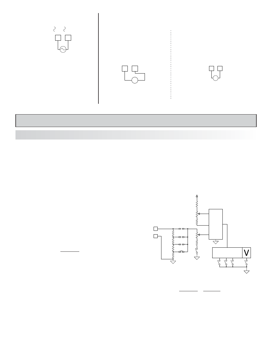
1K
9K
90K
900K
0-1.999V
0-19.99V
0-199.9V
0-300V
PROCESS
CIRCUITRY
+VDC
SCALE
POT
S5
S3
S2
S1
+SIGNAL
COMMON
S4
1.9.9.9
6
3.2 INPUT SIGNAL WIRING
Before connecting signal wires, the Input Range Jumper should be verified for proper position.
PAXLI
Current Signal (self powered)
Terminal 4: + Amps DC/AC
Terminal 3: - Amps DC/AC
PAXLV
Voltage Signal (self powered)
Terminal 4: + Volts DC/AC
Terminal 3: - Volts DC/AC
3
4
V
-
+
300V MAX.
SIGNAL
COMM
3
4
A
-
+
2A MAX.
COMM
SIGNAL
BLOCK DIAGRAM PAXLV
PAXLV
1
2
AC
AC
115/230
AC Power
Terminal 1: VAC
Terminal 2: VAC