Specifications, C2 asn, Batch – Red Lion C48C User Manual
Page 2: C2 asn = total
2
SPECIFICATIONS
1.
DISPLAY: 2 Line by 6 digit LCD display. Positive image reflective or
negative image transmissive with red (top line) and green (bottom line)
backlighting
Main Display: 0.3" (7.62 mm) high digits
Secondary Display: 0.2" (5.08 mm) high digits
Annunciators:
Value: PRS, 1, 2, and 3
Output: 01, 02, and 03.
2. POWER REQUIREMENTS:
AC Versions:
AC Power: 85 to 250 VAC, 50/60 Hz, 9 VA max.
DC Power: 11 to 14 VDC @ 150 mA max. (Non PNP output models)
Note: Models with PNP current sourcing outputs must be powered from AC.
DC Versions (C48XXX1X):
CONTINUOUS:
DC Power: 18 to 36 VDC; 5.5 W max.
AC Power: 24 VAC
±
10%; 50/60 Hz; 7 VA max.
Note: The +10% tolerance range on AC input voltage must be strictly
adhered to. DO NOT EXCEED 26.4 VAC.
PEAK (START-UP CURRENT):
AC or DC Power: 500 mA peak start-up current for 10 msec max.
DC OUT (V
SRC
IN) - Terminal 10
For units which do not have PNP current sourcing outputs, this terminal
provides a DC output for sensor power (+12 VDC +/-15%). The
maximum sensor current is 100 mA.
For units with PNP current sourcing outputs, this terminal serves a dual
purpose depending on the application’s PNP output voltage level and
current requirements.
1. The terminal may be used as a +12 VDC output for sensor power.
In this case, the PNP output voltage level will be +12 VDC
(
±
15%). A maximum of 100 mA is available for the combination
of sensor current and PNP output sourcing current.
2. If a higher PNP output voltage level or additional output sourcing
current is desired, an external DC supply may be connected
between the “DC OUT (V
SRC
IN)” and “COMM.” terminals. This
supply will determine the PNP output voltage level, and must be
in the range of +13 to +30 VDC.
An external DC supply can also provide the additional output
sourcing current required in applications where two or more PNP
outputs are “ON” simultaneously. However, the maximum current
rating of 100 mA per individual output must not be exceeded,
regardless of external supply capacity.
3. MEMORY: Nonvolatile E
2
PROM retains all programmable parameters and
count values.
4. SENSOR POWER: +12 VDC (
±
15%) @ 100 mA max.
5. COUNT INPUTS A & B: Accepts count pulses from a variety of sources,
DIP switch selectable.
Current Sourcing: 3.9K
Ω
pull-down, V
IN
max = 30 VDC
Current Sinking: 7.8K
Ω
pull-up to 12 VDC; I
SNK
= 1.8 mA max.
Debounce: 50 Hz max.
Lo Bias: V
IL
= 1.5 VDC max., V
IH
= 3.75 VDC min.
Hi Bias: V
IL
= 5.5 VDC max., V
IH
= 7.5 VDC min.
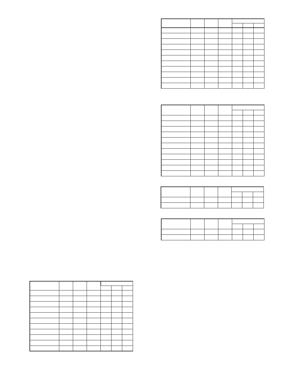
6. MAX. COUNT RATE: Model dependent. All listed values are in KHz.
Note: Max. count rates for X2 & X4 modes are given for 50 % duty cycle
signals and quad signals with 90° phase shift.
Single Preset Model C48CS
Dual Preset Model C48CD
Batch Model C48CB
With Counter 2 configured as a Batch Counter (
C2 ASn
=
bAtch
)
Batch Model C48CB
With Counter 2 configured as a Total Counter (
C2 ASn
= totAL
)
Prescaler Output Model C48CP
* - Inputs A & B rates summed.
7. USER INPUTS: Configurable as current sinking (active low) or current
sourcing (active high) inputs via a single plug jumper.
Current Sinking: V
IL
= 1.5 VDC max, 22 K
Ω
pull-up to 5 VDC.
Current Sourcing: V
IH
= 3.5 VDC min., V
IN
max = 30 VDC; 22 K
Ω
pull-
down.
Response Time = 10 msec max.
Inhibit Response Time = 250
µ
sec max.
8. OUTPUTS: (Output type and quantity, model dependent)
Solid-State:
NPN Open Collector: I
SNK
= 100 mA max. @ V
OL
= 1.1 VDC max.; V
OH
= 30 VDC max.
PNP Open Collector: I
SRC
= 100 mA max.(See note); V
OH
= 12 VDC
±15% (using internal supply); V
OH
= 13 to 30 VDC (using external
supply).
Note: The internal supply of the C48C can provide a total of 100 mA for
the combination of sensor current and PNP output sourcing current.
The supply voltage is +12 VDC (±15%), which will be the PNP output
voltage level when using only the internal supply.
If additional PNP output sourcing current or a higher output voltage
level is desired, an external DC supply may be connected between the
“DC Out/In” and “Comm.” terminals. This supply will determine the
PNP output voltage level, and must be in the range of +13 to +30 VDC.
An external supply can provide the additional output sourcing
current required in applications where two or more outputs are “ON”
simultaneously. However, the maximum rating of 100 mA per individual
output must not be exceeded, regardless of external supply capacity.
N/A
N/A
N/A
N/A
N/A
8
1.00000
N/A
N/A
N/A
N/A
N/A
6.2
0.00001-0.99999
X4
X2
X1
QUAD
*
Ad-Sub
Ad-Ad
C2-Usr
C2-Ud
C1-Usr
C1-Ud
PRESCALER
VALUE
2.1
4
4
8.6
3.6
8.5
1.00000
1.6
3.3
3.5
6.6
3.3
6.5
0.00001-0.99999
X4
X2
X1
QUAD
*
Ad-Sub
Ad-Ad
C2-Usr
C2-Ud
C1-Usr
C1-Ud
PRESCALER
VALUE
0.4
1
1.4
2.2
0.9
1.9
9.00001-9.99999
0.5
1.1
1.5
2.4
1.1
2.2
8.00001-9
0.6
1.2
1.6
2.6
1.1
2.4
7.00001-8
0.6
1.3
1.7
2.8
1.3
2.7
6.00001-7
0.7
1.5
1.9
3.2
1.4
2.9
5.00001-6
0.8
1.7
2.1
3.8
1.7
3.4
4.00001-5
1
2
2.4
4.2
2
4.1
3.00001-4
1.3
2.5
2.8
5.4
2.5
5
2.00001-3
1.6
3
3.2
3.7
6.6
3.2
6.5
1.00001-2
3
4.2
4.3
11.8
5.5
11.4
1.00000
2.2
3.6
8.4
4.1
8.3
0.00001-0.99999
X4
X2
X1
QUAD
*
Ad-Sub
Ad-Ad
C2-Usr
C2-Ud
C1-Usr
C1-Ud
PRESCALER
VALUE
0.4
0.9
1.5
2
0.9
1.9
9.00001-9.99999
0.5
1.1
1.6
2.3
0.9
2.2
8.00001-9
0.6
1.2
1.8
2.4
1.1
2.2
7.00001-8
0.6
1.3
2
2.8
1.3
2.7
6.00001-7
0.7
1.4
2.2
3.2
1.4
2.9
5.00001-6
0.8
1.7
2.5
3.8
1.7
3.4
4.00001-5
1
2
2.8
4.4
2
4.1
3.00001-4
1.3
2.5
3.4
5.2
2.4
5
2.00001-3
1.6
3.2
4
6.6
3.2
6.5
1.00001-2
3
5.8
6
11.5
5.7
11.5
1.00000
2.1
4.1
4.5
8.6
4.1
8.3
0.00001-0.99999
X4
X2
X1
QUAD
*
Ad-Sub
Ad-Ad
C2-Usr
C2-Ud
C1-Usr
C1-Ud
PRESCALER
VALUE
PRESCALER
VALUE
C1-Usr
C1-Ud
C2-Usr
C2-Ud
*
Ad-Sub
Ad-Ad
QUAD
X1
X2
X4
0.00001-0.99999
8.4
4.1
9.4
5.4
4.5
2.1
1.00000
12
5.9
12.4
6.5
6
3
1.00001-2
6.6
3.2
6.8
4.3
3.3
1.6
2.00001-3
5.3
2.6
5.6
3.7
2.6
1.3
3.00001-4
4.3
2.1
4.6
3
2.2
1.1
4.00001-5
3.6
1.8
3.8
2.7
1.8
0.9
5.00001-6
3.1
1.5
3.4
2.4
1.6
0.8
6.00001-7
2.8
1.4
3.2
2.1
1.4
0.7
7.00001-8
2.6
1.3
2.8
1.9
1.3
0.6
8.00001-9
2.3
1.1
2.4
1.8
1.1
0.5
9.00001-9.99999
2.1
1
2.3
1.7
1.1
0.5