Hms110/112 installation – Vaisala HMDW110 User Manual
Page 19
2. Open the transmitter cover, and route the cable through the cable gland.
Connect the wires to the screw terminals according to the wiring
instructions:
o
o
Wiring HMDW110 with RDP100 on page 21
For the arrangement of the screw terminals, see section Component Board
on page 11.
3. Tighten the cable gland and close the transmitter cover.
4. Remove the yellow transport protection cap from the probe.
HMS110/112 Installation
n
Medium size crosshead screwdriver (Pozidriv).
n
Small slotted screwdriver for screw terminals.
n
Tools for cutting and stripping wires.
n
19 mm open-end wrench for tightening the cable gland.
Additional tools for pole installation:
n
Zip ties for securing the cable to the pole.
Additional tools for wall installation:
n
Drill and bits.
n
Screws (2 pcs, Ø < 5.5 mm) and wall plugs.
n
Cable clips for securing the cable to the wall.
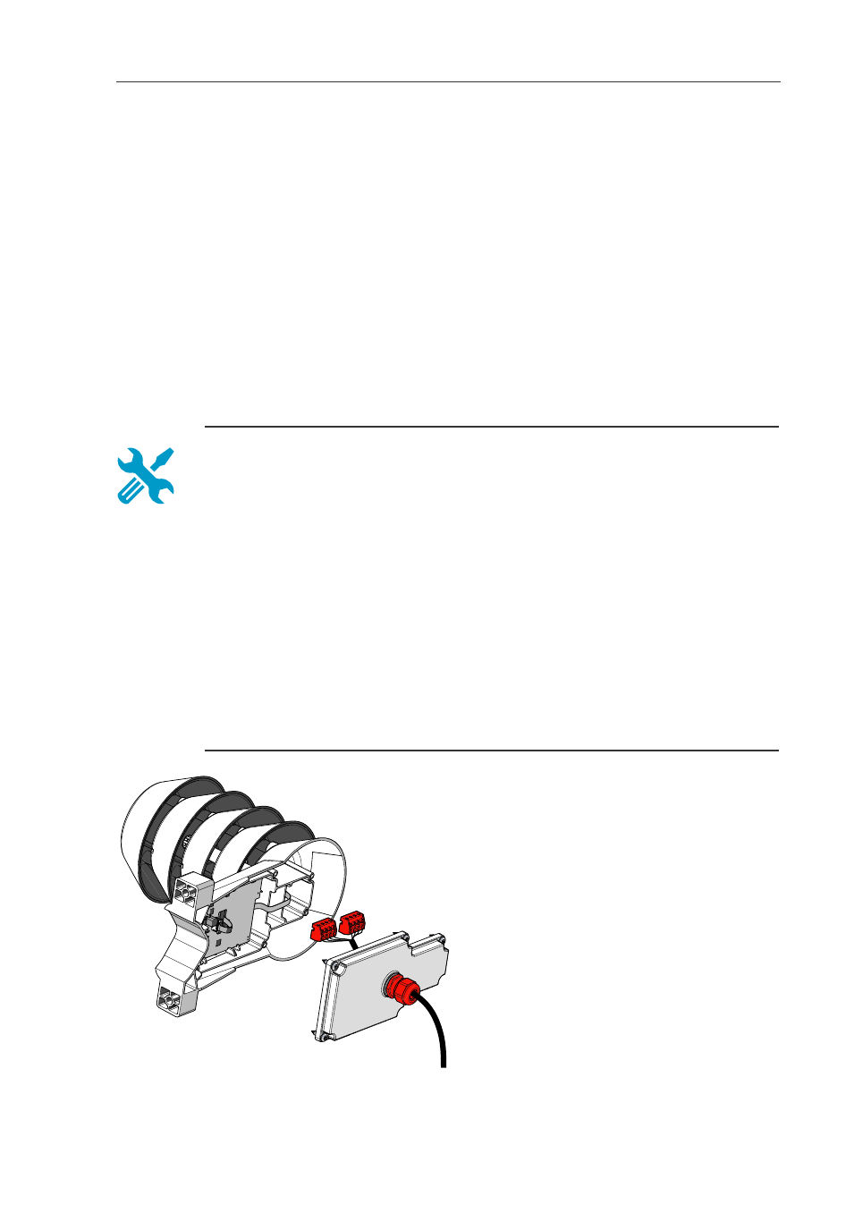
1. Open the six screws that hold the
transmitter cover.
2. Route the power and signal cable
through the cable gland, and
connect the wires to the screw
terminals according to the wiring
instructions:
o
o
Wiring HMDW110 with
RDP100 on page 21
For the arrangement of the screw
terminals, see section
Component Board on page 11.
17
3 Installation