DAVIS SensorLink for Weather Monitor and Wizard User Manual
I n k
Product # 7610 & 7611
S
E N S O R
L
I N K
™
I
N S T A L L A T I O N
M
A N U A L
The SensorLink Transmitter (#7610) and SensorLink Receiver (#7611) are
designed to work with Davis Instruments’ Weather Monitor II
®
and the
Weather Wizard III
®
to enable wireless transmission of data between the sen-
sors and console up to 400 feet (120 m). The SensorLink Transmitter/Receiver
pair takes the place of the junction box and cable that would normally connect
the outdoor sensors to the display console. The outdoor sensors connect to the
transmitter while the display console connects to the receiver.
One transmitter can send data to any number of Monitor II or Wizard III con-
soles, providing the console contains an receiver. The transmitter/receiver
communicate on one of 8 different ID codes set by the user. This allows multi-
ple systems to coexist in the same geographical area.
Note:
SensorLink operates on a low power frequency that does not require an FCC license.
C
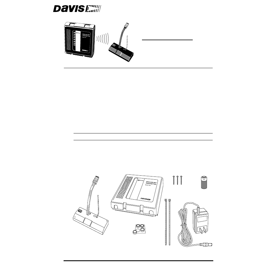
OMPONENTS
The SensorLink package includes the following. Please make sure you have
everything you need before beginning.
Receiver
Transmitter
#6 x 1" (25 mm long)
Self-Threading Screws
Cable Ties
3 Volt
Lithium
Transmitter
Battery
Power Adapter
Adhesive Pads
(not used)
RECEIVER COMPONENT
TRANSMITTER COMPONENTS
Document Outline
- SensorLink™
- The SensorLink Transmitter (#7610) and SensorLink Receiver (#7611) are designed to work with Da...
- Components
- Tools and Materials Needed
- Configuring Transmitter/Receiver Pair
- ID Code
- Dip Switch 1
- Dip Switch 2
- Dip Switch 3
- Silent Operating Mode
- Test Mode
- Installation
- The instructions below will take you through the process required to install the transmitter and ...
- Choosing a Location for Transmitter and Receiver
- Installing Transmitter and Receiver
- 1. Remove the cables from your existing junction box.
- 2. Remove the cover from the transmitter by pushing down on the tabs at the top until you can rem...
- 3. Attach the base to the mounting surface using the #6 x 1” screws.
- 4. Insert the sensor cables in the appropriate jacks, as shown below.
- 5. Gather the sensor cables and secure them to the cable tie lug using a cable tie.
- 6. Apply power to the transmitter using one of the options indicated below.
- 7. Test the transmitter by setting dip switch #4 to the “Test” position, as shown below.
- 8. Install the receiver into the console base and apply power as shown below.
- Testing Reception
- 1. Move dip switch #4 on the receiver to the position opposite its starting position.
- Troubleshooting
- Specifications
- FCC Part 15 Class B Registration Warning
- This equipment has been tested and found to comply with the limits for a class B digital device, ...
- If this equipment does cause harmful interference to radio or television reception, which can be ...
- Shielded cables and I/O cords must be used for this equipment to comply with the relevant FCC reg...