DAVIS GroWeather/EnviroMonitor: Systems Installation User Manual
Page 6
System Installation
Page 6
Industrial System Installation Manual
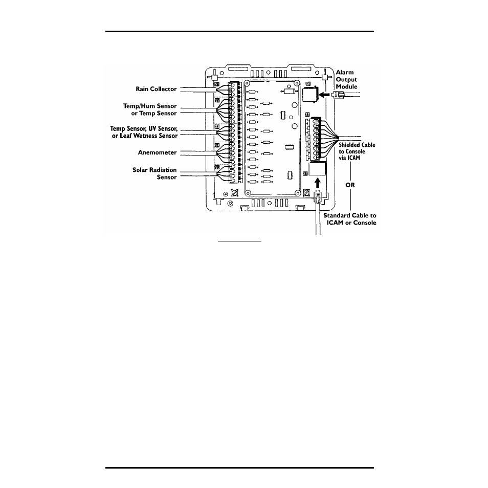
2. Attach the sensor cables to the appropriate terminals (as shown below) using the wire
colors printed on the circuit board.
A
TTACHING
C
ABLES
✦
The drain wire (the uninsulated shield wire) from each cable con-
nects to the terminal with the triangle next to it.
✦
When using an extension cable, any extra conductors which are not
used at the sensor cable-to-extension cable connection should be
clipped off to avoid problems at any subsequent connections.
✦
When two color codes are listed together, it indicates that two wires
should be used as a single wire. Twist both wires together before
inserting into the terminal.
✦
Color codes in parenthesis indicate any additional wire color assign-
ments for
extension cables
. If using an extension cable to connect to
the SIM, twist both listed wires together before inserting into the ter-
minal. If connecting to the SIM with the sensor cable, ignore the
color code in parenthesis.
- Envoy8X Getting Started Guide (16 pages)
- Vantage Pro2 Long Range Repeater Installation Addendum (16 pages)
- Wireless Temperature Station (6372) Installation Manual (12 pages)
- Solar Power Kit For Vantage Weather Stations and Envoy8X (8 pages)
- Energy EnviroMonitor: Console (63 pages)
- EZ-Mount Installation (16 pages)
- Gro/Energy/Health Installation (24 pages)
- GroWeather Console (65 pages)
- Health EnviroMonitor: Console (60 pages)
- Anemometer (7911, 7914) (8 pages)
- Rain Collector II for GroWeather, EnviroMonitor, Weather Monitor and Wizard (16 pages)
- Sensor - UV for GroWeather or EnviroMonitor (16 pages)
- Solar Radiation Sensor for GroWeather and EnviroMonitor (16 pages)
- Temperatur/Humidity Sensor for GroWeather, EnviroMonitor, & Weather Monitor (12 pages)
- Temperature Sensor/Probe for GroWeather, EnviroMon., Weather Monitor/Wizard (4 pages)
- GroWeatherLink Software (108 pages)
- GroWeatherLink/ET Data Logger (2 pages)
- Short-Range Modem Pair: Perception, GroWeather, EnviroMon., Monitor, Wizard (8 pages)
- Alarm Output Module (16 pages)
- Cable Coupler Kit (4 pages)
- Cable Crimp-Type Splice Connector (4 pages)
- Complete System Shelter (12 pages)
- Fan-Aspirated Radiation Shield (24 pages)
- Grounding Kit (4 pages)
- Interface Cable Adapter Module (8 pages)
- Mounting Pole Kit Installation (4 pages)
- Mounting Tripod Kit (8 pages)
- Multi-purpose Shelter (12 pages)
- Radiation Shield (7714) (16 pages)
- Radio Surge Protector (4 pages)
- Rain Collector Heater (12 pages)
- Rain Collector Shelf: GroWeather, EnviroMonitor, Weather Monitor & Wizard (8 pages)
- Second Solar Panel for EZ-Mount Solar Power Kit (4 pages)
- Sensor Mounting Arm for GroWeather, EnviroMonitor, Weather Monitor & Wizard (16 pages)
- Sensor Tilting Bracket for GroWeather or EnviroMonitor (8 pages)
- Shelter Heaters (12 pages)
- Solar Power Kit for Non-Vantage Pro Stations (16 pages)
- Surge Protector (2 pages)
- Surge Protector Shelter - Large (8 pages)
- Surge Protector Shelter - Small (4 pages)
- Terminal Box for sensors/interface module, communication lines: GroWeather (8 pages)
- WeatherLink for Windows 4.0 (116 pages)
- WeatherLink Getting Started Guide (20 pages)
- WeatherLink Mac OS X Getting Started Guide (16 pages)