JKS 6125 User Manual
Page 2
JKS6125
JKS Adjustable Control Arm Installation
2 Page
Remove the lower suspension arm nut and bolt
from the axle housing bracket. Retain the original
mounting hardware.
Remove the nut and bolt from the chassis rail
bracket. Retain the original mounting hardware.
Remove the original lower suspension arm from
the vehicle.
2. SET CONTROL ARM LENGTH
Adjustable Control Arms are fully collapsed when supplied
from JKS and must be adjusted to the desired lengths
before installation.
The working length of each lower Control Arm can be in-
creased (up to 2.25” longer), decreased (up to 1.0” short-
er), or exactly the same as the OE suspension arm.
Determine ideal Control Arm length for your ap-
plication by considering factors such as:
Â
Length of OE suspension arm
Â
Tire Clearance
Â
Pinion Angle
Rotate adjustable end of Control Arm until the
desired length is achieved.
Adjust corresponding Control Arm to exact same
length.
3. INSTALL ADJUSTABLE CONTROL ARM
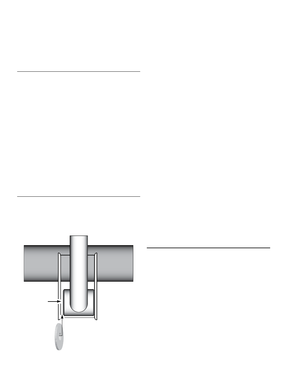
The factory suspension arm brackets on the chassis and
axle are wider than the Adjustable Control Arm bushings.
Therefore, it will be necessary to insert flat washer shims
between the bracket and bushing to fill this void.
Use flat washer shims
to fill void between
bracket and bushing
VOID
9/16” SAE
FLAT
WASHER
IMPORTANT: Each Control Arm requires three (3) flat
washer shims for installation. Two (2) flat washers are
required for the chassis end of the Control Arm, and
one (1) flat washer is required for the axle end.
For your convenience, enough flat washer shims have
been supplied to accommodate installation of front and
rear lower Control Arms.
Apply anti-seize lubricant to bolt threads of original
mounting hardware.
Mount the non-rotating (BLACK) end of Adjustable
Control Arm to the chassis rail bracket with the
greaseable fitting facing up.
Insert two (2) flat washer shims – one on each
side of bushing – to fill the void between the chas-
sis bracket and Control Arm bushing.
HINT: Flat
washers must be installed to ensure proper bush-
ing performance and reliability.
Install the original mounting bolt and finger tighten
the nut.
DO NOT torque mounting hardware until
instructed.
Mount the rotating (GOLD) end of Adjustable Con-
trol Arm to the axle housing bracket.
Insert one (1) flat washer shim to fill the void
between the axle bracket and Control Arm bush-
ing. HINT: Flat washer must be installed to ensure
proper bushing performance and reliability.
Install the original mounting bolt and finger tighten
the nut.
DO NOT torque mounting hardware until
instructed.
HINT: If mounting bolt is difficult to install due to misalign-
ment of Control Arm bushing with mounting bracket, either
(1) adjust height of axle housing with hydraulic jack, (2)
move axle housing into position with a heavy-duty ratchet
strap, or (3) temporarily disconnect track bar until mounting
holes align.
4. TIGHTEN MOUNTING HARDWARE
Once both Adjustable Control Arms have been
properly installed, lower the vehicle to the ground
until coil springs are supporting the full weight of
vehicle.
Using a torque wrench, tighten the mounting hard-
ware to 130 ft-lbs.