X” – 3/8” = ride height, Do not exceed – JKS 2570 User Manual
Page 3
JKS Adjustable Coil Spacer Installation
PN 2570
Page 3 of 4
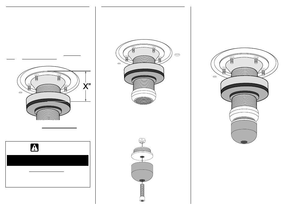
4. SET ADJUSTER RING FOR
DESIRED RIDE HEIGHT
Apply spray lubricant to threaded portion of
Main Body (A).
Install Adjuster Ring (B) by threading it onto the
Main Body (A).
Slide Isolator Pad (C) onto Main Body (A) until
flush with Adjuster Ring (B).
IMPORTANT: Vehicle ride height is determined by
measuring the distance between the top of Main
Body and bottom of Isolator Pad, and then
subtracting 3/8
” (0.375 in.).
X
” – 3/8” = RIDE HEIGHT *
* Represents increase in ride height over OE suspension
WARNING
DO NOT EXCEED
MAXIMUM RANGE OF ADJUSTMENT
ADJUSTMENT RANGE *
MINIMUM: 2
” (2.0 in.)
MAXIMUM: 4
” (4.0 in.)
Rotate Adjuster Ring (B) to desired position and
tighten the recessed 3/8
” x 1-1/4” Cap Bolt (K)
to lock in place.
5. INSTALL BUMP STOP ON
THREADED TUBE OF ACOS
Apply a drop of thread locking compound to
bottom few threads of Main Body (A).
Install Bump Stop Adapter (D) onto Main Body
(A) and tighten by hand until snug.
Insert the 10mm x 55mm Cap Bolt (H) into the
recessed hole in Polyurethane Bump Stop (G)
and through the hole in the bottom of the Bump
Stop Plug (F).
Secure the Polyurethane Bump Stop (G) to
the Bump Stop Plug (F) by installing the
10mm Locking Nut (E).
Slowly tighten 10mm x 55mm Cap Bolt (H) until
the sides of the Polyurethane Bump Stop (G)
begin to bulge. Do NOT overtighten!
Apply anti-seize lubricant to threads of Bump
Stop Plug (F).
Install Bump Stop Plug (F) with Polyurethane
Bump Stop (G) by threading the assembly
completely into the Bump Stop Adapter (D).
Tighten by hand until snug.