Boonton 9240 series rf voltmeter, Getting started 3-2 – Boonton 9240 RF Voltmeter User Manual
Page 28
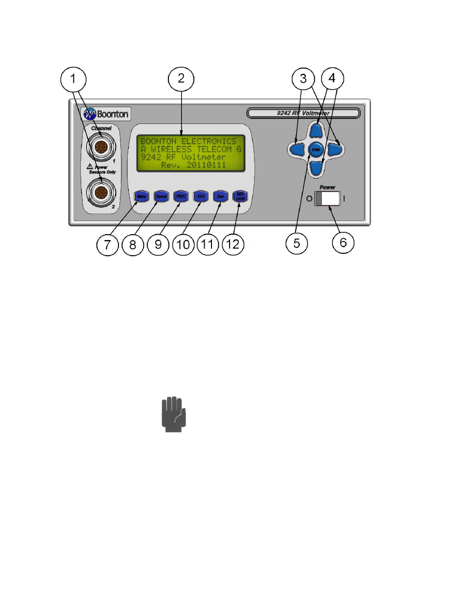
Boonton 9240 Series RF Voltmeter
Figure 3-1. Standard 9240 Series RF Voltmeter - Front Panel
Table 3-1 Operating Controls, Indicators and Connections
Reference #
Front Rear Nomenclature
Function
1
1
Channel Inputs
One or two Channel inputs are located on the front, or optionally on the rear
panel of the instrument. These are 10-pin precision connectors designed to accept
only Boonton RF Voltage Probes.
Caution
Do not attempt to connect anything other than a
Boonton Voltage Probe and Data Adapter to the Channel inputs! The
Channel inputs are not measurement terminals and cannot be used for
other than the intended purpose.
2 Display
Screen
LCD
readout
of the measurements and user interface for editing of the
instrument's operating parameters.
Getting Started
3-2