4 preliminary check, 4 preliminary check -3, Boonton 9240 series rf voltmeter – Boonton 9240 RF Voltmeter User Manual
Page 25: Installation 2-3
Boonton 9240 Series RF Voltmeter
2.4 Preliminary Check
The following preliminary check verifies that the instrument is operational and has the correct software installed. It should
be performed before the instrument is placed into service. To perform the preliminary check, proceed as follows:
1. Connect the AC (mains) power cord to a suitable AC power source; 90 to 264 volts AC, 47 to 63 Hz, with a
capacity in excess of 75 W. The power supply will automatically adjust to voltages within this range.
2. Attach the probe Data Adapter(s) to the front panel CHANNEL connector(s).
3.
Set the POWER switch to the ON (1) position.
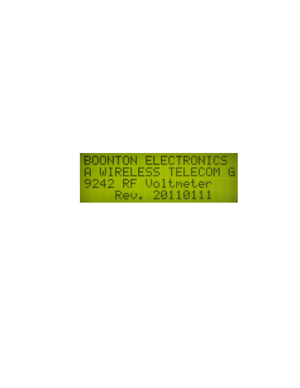
4. Verify that "BOONTON ELECTRONICS, 9242 RF Voltmeter, Rev. XXXXXXXX" is momentarily displayed
where XXXXXXXX represents the revision code. (Note: Model number 9241 display for single channel
instruments.) While the sign-on screen is displayed the phrase “ A WIRELESS TELECOM GROUP
COMPANY” is scrolled along the second line.
5. Verify that the measurement display showing "CH 1" only for Model 9241 or "CH 1" and "CH 2" for Model
9242. Other data on the display will depend upon previous settings.
6. Press the