3 pulsed rf operation diode sensors, Duty cycle (%) p u lse p o wer (db m ) – Boonton Power Sensor User Manual
Page 39
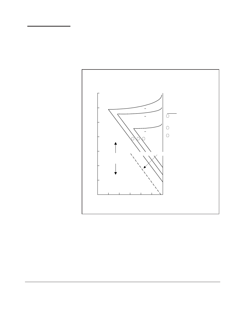
Figure 5-3. Pulsed Accuracy for Diode Sensors
5-3 Pulsed RF Operation Diode Sensors
Figure 5-3 shows the valid operating region for the Diode Sensors. As with Thermal
Sensors, the bottom end measurement is limited by noise, getting worse as the duty
cycle decreases. At the top end, the limitation is on pulse power because even a very
short pulse will charge up the detecting capacitors. The burnout level for Diode Sensors
is the same for the pulsed and CW waveforms. The minimum pulse repetition frequency
is 10 kHz.
32 Power Sensor Manual
-60
.01
.1
1
10
100
Duty Cycle (%)
P
u
lse P
o
wer (dB
m
)
-20
-30
-40
-50
-10
0
.001
Operation in this
region not valid
RMS Noise = 65pW @ 2.8 sec filter
<0.1 dB
<0.5 dB
<0.2 dB
2
2
2
Notes:
1
For 51015, 51016 and 51078
sensors, add 10, 20 and 30 dB
to the vertical axis respectively.
2
For 10 second filtering, drop
this line by 3 dB.
3
These figures are to be added
to the standard CW accuracy
figures.
34