Boonton Power Sensor User Manual
Page 21
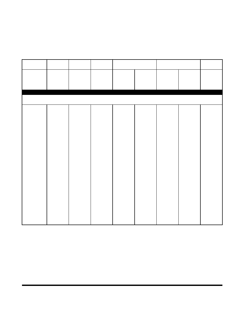
Sensor characteristics of Boonton legacy Peak Power Sensors are presented in
table 2-5. This data is presented for reference only. Contact the sales department
for availability.
Table 2-5. Legacy Peak Power Sensor Characteristics
Model
Frequency
Power Overload
Rise Time
Maximum SWR
Drift & Noise
Range
Measurement
Rating
@ 0 dBm
Peak
Fast
Slow
Impedance
CW
(1)
Peak Power
High
Low
Frequency
SWR
Peak Power
RF Connector
Int. Trigger
CW Power
Bandwidth
Bandwidth
CW Power
(GHz)
(dBm)
(ns)
(ns)
(GHz)
DUAL DIODE PEAK POWER SENSORS
Sensors below are for use with 4400, 4500, 4400A and 4500A RF Peak Power Meters and
4530 Series RF Power Meter when combined with Model 2530 1 GHz calibrator accessory.
56218-S2
0.03 to 26.5
-24 to 20
1W for 1 us
< 150
< 500
to 2
1.15
4 uW
50
Ω
-34 to 20
200 mW
(3 MHz)
(700 kHz)
to 6
1.20
0.4 uW
K(M)
-10 to 20
to 18
1.25
(3)
to 26.5
1.50
56226
0.03 to 26.5
-24 to 20
1W for 1 us
< 150
< 500
to 1
1.15
4 uW
50
Ω
-34 to 20
200 mW
(3 MHz)
(700 kHz)
to 6
1.20
0.4 uW
K(M)
-10 to 20
to 18
1.25
(3)
to 26.5
1.50
56340
0.5 to 40
-24 to 20
1W for 1 us
< 15
(2)
< 200
to 4
1.25
4 uW
50
Ω
-34 to 20
200 mW
(35 MHz)
(1.75 MHz)
to 38
1.65
0.4 uW
K(M)
-10 to 20
to 40
2.00
(3)
56526
0.5 to 26.5
-40 to 20
1W for 1 us
< 100
< 300
to 2
1.15
50 nW
50
Ω
-50 to 20
200 mW
(6 MHz)
(1.16 MHz)
to 4
1.20
5 nW
K(M)
-27 to 20
to 18
1.45
(4)
to 26.5
1.50
56540
0.5 to 40
-40 to 20
1W for 1 us
< 100
< 300
to 4
1.25
50 nW
50
Ω
-50 to 20
200 mW
(6 MHz)
(1.16 MHz)
to 38
1.65
5 nW
K(M)
-27 to 20
to 40
2.00
(4)
NOTES: 1) Models 4400, 4500, 4400A and 4500A only.
2) Models 4531 and 4532: <20ns, (20MHz).
3) Shaping Error (Linearity Uncertainty), all levels 2.3%
4) Shaping Error (Linearity Uncertainty), all levels 4.7%
16
Power Sensor Manual