Section 2, Power sensor characteristics – Boonton Power Sensor User Manual
Page 10
2
Power Sensor Characteristics
The power sensor has three primary functions. First the sensor converts the incident
RF or microwave power to an equivalent voltage that can be processed by the power
meter. The sensor must also present to the incident power an impedance which is
closely matched to the transmission system. Finally, the sensor must introduce the
smallest drift and noise possible so as not to disturb the measurement.
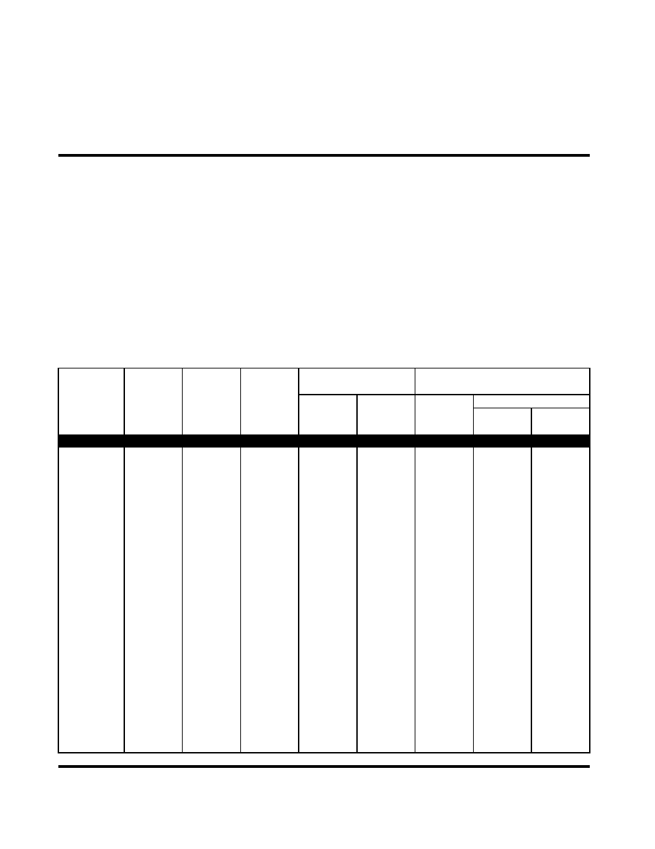
Table 2-1 lists the characteristics of the latest line of Continuous Wave (CW) sensors
offered by Boonton. The latest Peak Power sensor characteristics are outlined in Table
2-2. This data should be referenced for all new system requirements.
Table 2-1. Diode and Thermal CW Sensor Characteristics
Model
Frequency
Range
Dynamic
Range
(1)
Overload
Rating
Maximum SWR
Drift and Noise
@ 0 dBm
Lowest Range
Impedance
Peak Power
Drift (typ.)
Noise
RF Connector
CW Power
Frequency
SWR
1 Hour
RMS
2 σ
(dBm)
(GHz)
(typical)
WIDE DYNAMIC RANGE DUAL DIODE SENSORS
51075
500 kHz
-70 to +20
1 W for 1µs
to 2
1.15
100 pW
30 pW
60 pW
50
Ω
to 18 GHz
(2)
300 mW
to 6
1.20
(6)
N(M)
to 18
1.40
51077
500 kHz
-60 to +30
10 W for 1µs
to 4
1.15
2 nW
300 pW
600 pW
50
Ω
to 18 GHz
(3)
3 W
to 8
1.20
(7)
GPC-N(M)
to 12
1.25
to 18
1.35
51079
500 kHz
-50 to +40
100 W for 1µs
to 8
1.20
20 nW
3 nW
6 nW
50
Ω
to 18 GHz
(4)
25 W
to 12
1.25
(7)
GPC-N(M)
to 18
1.35
51071
10 MHz
-70 to +20
1 W for 1µs
to 2
1.15
100 pW
30 pW
60 pW
50
Ω
to 26.5 GHz
(2)
300 mW
to 4
1.20
(7)
K(M)
to 18
1.45
to 26.5
1.50
51072
30 MHz
-70 to +20
1 W for 1µs
to 4
1.25
100 pW
30 pW
60 pW
50
Ω
to 40 GHz
(2)
300 mW
to 38
1.65
(7)
K(M)
to 40
2.00
Power Sensor Manual
5