2 pulsed rf operation thermocouple sensors, Duty cycle (%) puls e power (dbm) – Boonton Power Sensor User Manual
Page 38
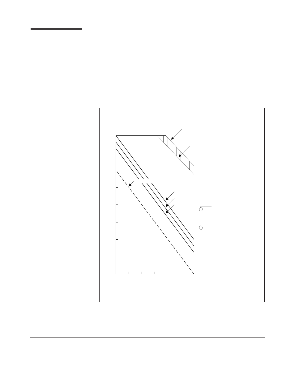
Figure 5-2. Pulsed Accuracy for Thermocouple Sensors
5-2 Pulsed RF Operation Thermocouple Sensors
Figure 5-2 shows the regions of valid duty cycle and pulse power that apply to the
Thermal Sensors. As the duty cycle decreases, the average power decreases for a
given pulse power and the noise becomes a limitation. Also, there is a pulse power
overload limitation. No matter how short the duty cycle is, this overload limitation
applies. Lastly, the average power cannot be exceeded (there is some headroom between
the measurement limitation and the burnout level of the sensor).
Since the detection process in Thermal Sensors is heat, Thermal Sensors can handle
pulse powers that are two orders of a magnitude larger than their maximum average
power. This makes them ideal for this application. The minimum pulse repetition
frequency for the Thermal Sensors is approximately 100 Hz.
Power Sensor Manual 31
-30
.01
.1
1
10
100
Duty Cycle (%)
Puls
e Power (dBm)
10
0
-10
-20
20
30
.001
Operation in this
region not valid
Valid
measurement
region
RMS Noise = 100 nW @ 4.8 sec filter
<0.1 dB
<0.3 dB
<0.2 dB
Average
overload
limitation
(300mW)
Upper
measurement
limitation
(100mW Avg Power)
Notes:
1
For 51200 and 51300 sensors,
add 20 dB to vertical axis. For
51201 and 51301 sensors, add
24 dB to vertical axis.
2
These accuracy figures are to
be added to the standard CW
accuracy figures.
33