Boonton Power Sensor User Manual
Page 15
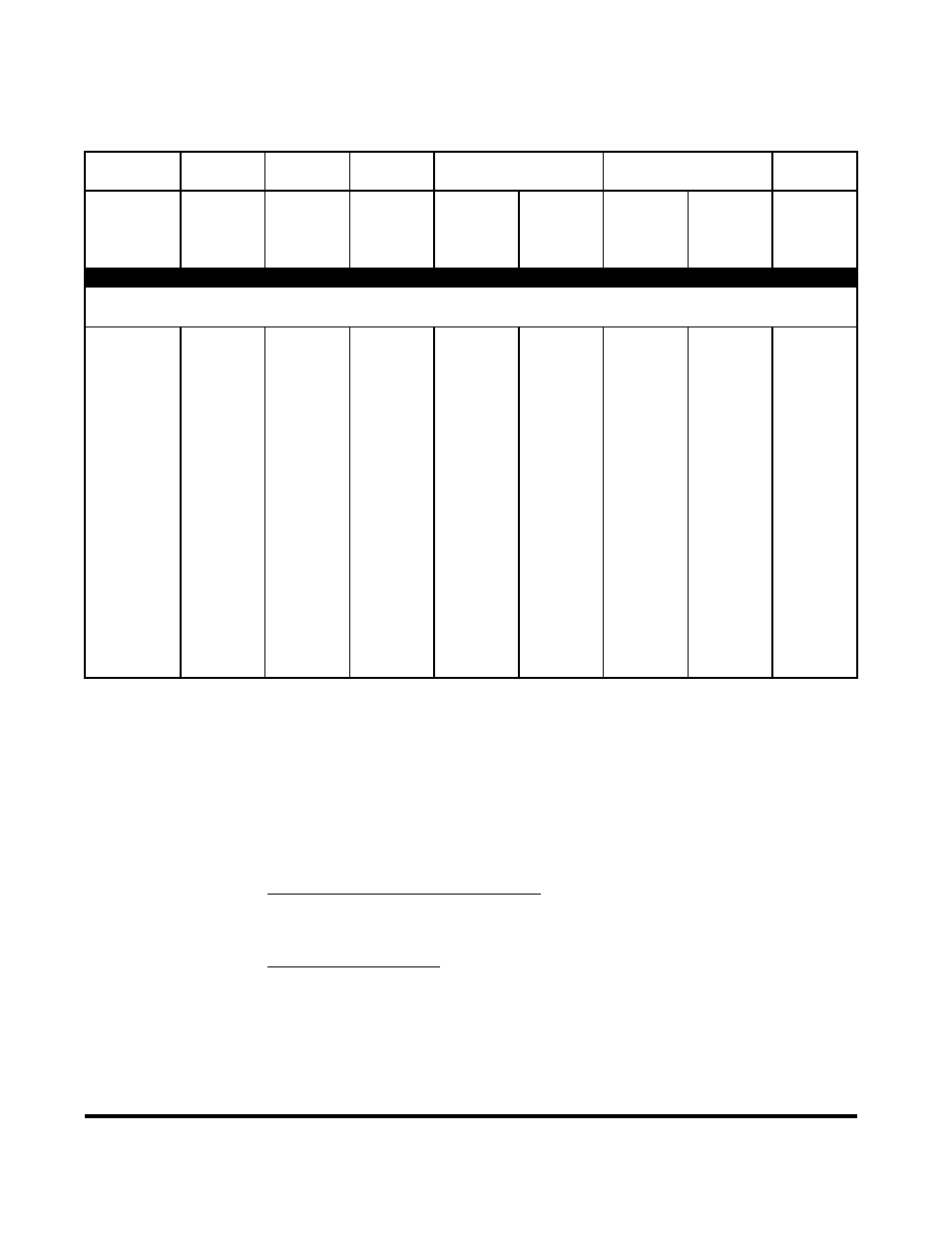
Table 2-2. Peak Power Sensor Characteristics (con't.)
Model
Frequency
Power Overload
Rise Time
Maximum SWR
Drift & Noise
Range
Measurement
Rating
@ 0 dBm
Peak
Fast
Slow
Impedance
CW
(1)
Peak Power
High
Low
Frequency
SWR
Peak Power
RF Connector
Int. Trigger
CW Power
Bandwidth
Bandwidth
CW Power
(GHz)
(dBm)
(ns)
(ns)
(GHz)
DUAL DIODE PEAK POWER SENSORS
Sensors below are for use with 4400, 4500, 4400A, 4500A and 4530.
Compatible with 4530 Series internal 50 MHz calibrator.
57318
0.5 to 18
-24 to 20
1W for 1 us
< 15
(2)
< 10 us
to 2
1.15
4 uW
50
Ω
(0.05 to 18)
-34 to 20
200 mW
(35 MHz)
(350 kHz)
to 16
1.28
0.4 uW
N(M)
-10 to 20
to 18
1.34
(3)
57340
0.1 to 40
-24 to 20
1W for 1 us
< 15
(2)
< 10 us
to 4
1.25
4 uW
50
Ω
(0.03 to 40)
-34 to 20
200 mW
(35 MHz)
(350 kHz)
to 38
1.65
0.4 uW
K(M)
-10 to 20
to 40
2.00
(3)
57518
0.1 to 18
-40 to 20
1W for 1 us
< 100
< 10 us
to 2
1.15
50 nW
50
Ω
(0.05 to 18)
-50 to 20
200 mW
(6 MHz)
(350 kHz)
to 6
1.20
5 nW
N(M)
-27 to 20
to 16
1.28
(4)
to 18
1.34
57540
0.1 to 40
-40 to 20
1W for 1 us
< 100
< 10 us
to 4
1.25
50 nW
50
Ω
(0.05 to 40)
-50 to 20
200 mW
(6 MHz)
(350 kHz)
to 38
1.65
5 nW
K(M)
-27 to 20
to 40
2.00
(5)
NOTES: 1) Models 4400, 4500, 4400A and 4500A only.
2) Models 4531 and 4532: <20ns, (20MHz).
3) Shaping Error (Linearity Uncertainty), all levels 2.3%
4) Shaping Error (Linearity Uncertainty), all levels 4.0%
5) Shaping Error (Linearity Uncertainty), all levels 4.7%
Frequency calibration factors (NIST traceable) and other data are stored within
all the Peak Power Sensors. Linearity calibration is performed by the built-in
calibrator of the peak power meter.
MODELS 4400, 4500, 4400A and 4500A:
All Peak Power sensors can be used with these models and calibrated with the
internal 1GHz step calibrator unless otherwise noted.
MODELS 4531 and 4532:
The Peak Power sensors in the lower group above may be used with these models
and calibrated with the internal 50 MHz step calibrator. The sensors on the upper
group may be used if the Model 2530 1 GHz Accessory Calibrator is used for
calibration.
A five-foot long sensor cable is standard. Longer cables are available at a higher
cost. Effective bandwidth is reduced with longer cables.
10
Power Sensor Manual