BMR Suspension TAS005 User Manual
Page 9
(CONTINUED)
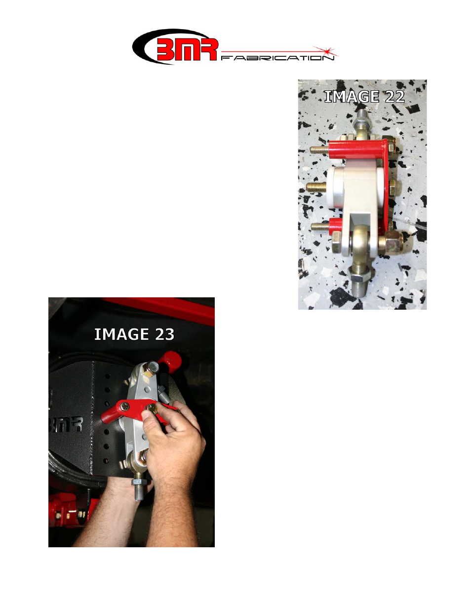
44. The next few steps involve mounting the Watts Link.
Locate the billet aluminum Watts pivot, the double
shear reinforcement plate, (2) 3/8” x 3.75” bolts, and a
½” x 4” bolt. Refer to Image 22 for a visual
representation of these components assembled. NOTE:
If your vehicle will be setup for a low ride height,
choose one of the lower sets of mounting holes to install
the Watts pivot. For most applications, this is a good
starting point. This mounting point, along with the
outer Watts linkage mounting points, determines the
vehicles rear roll center (RC) height. Variances in
vehicle center-of-gravity (CG) height make multiple
mounting locations necessary for fine tuning RC height.
45. Once a mounting location has been
determined, tighten the center bolt to 80
ft/lbs. and the smaller outer bolts to 35 ft/lbs.
(Image 23)
46. Before mounting the Watts link bars, it is
necessary to load the vehicles suspension.
Allow the weight of the vehicle to sit on the
rear end and bounce the car a few times to
settle the suspension. If the car sits too high
or too low, use the provided spanner wrench
at this time to adjust the spring height on the
shocks. If it is not possible to adjust the
springs enough to achieve the desired ride
height, move the lower shock mounting hole
to a different location. Once the desired ride
height is established, tighten the collar on
the shock and proceed to the following step.
9