BMR Suspension TAS005 User Manual
Page 5
5
(CONTINUED)
22. Once properly positioned, locate the
provided sheet metal screws in the hardware
pack. As shown in Image 11, screw the
cross-member into each frame rail to hold it
into position for the upcoming steps.
NOTE: the cross-member should draw up
tight against the frame rail. Any floor pan
deformations that prevent the cross-member
from fitting flush against the frame rail
should be adjusted using a pry-bar or
rubber mallet.
23. At this step the cross-member may be
welded to the subframe or bolted. If bolting
is preferred, proceed to step 24. If welding
is preferred, remove the cross-member and
prep it for welding by grinding the
powdercoat off at the weld points. Remove
all paint, undercoating and scale from the
weld area on the subframe then re-install the
cross-member. Weld a full 2” bead
vertically on each end of the plate and at
least 4 inches of weld horizontally on each
side. Wire brush and paint the weld area
with rust preventive paint. Proceed to step
30.
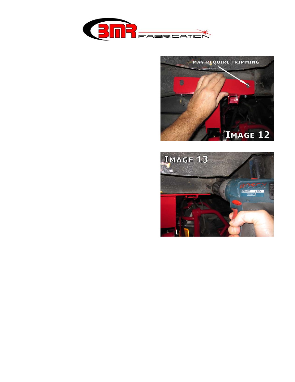
24. If bolting the cross-member into place,
begin on the passenger side. Position the
provided frame reinforcement plate as shown in Image 12. The outside perimeter of the
reinforcement plate should match that of the shock cross-member.
25. Mark the frame at the center of the slot using a grease pencil or paint marker. NOTE:
Due to vehicle production variance, it may be necessary to trim the forward portion of
the reinforcement plate slightly in order to make it fit squarely to the shock cross-
member. The factory shock reinforcement on the frame rail may prevent proper plate
alignment if the reinforcement plate is not trimmed. Plate alignment is very important to
insure the holes are drilled in the proper location to line up squarely with the shock
cross-member holes on the other side of the frame rail.
26. Center-punch the marks on the frame to provide a drill centerline so the drill bit doesn’t
wander.
27. The recommended (and easiest) way to drill through the frame rails is with a step-type
drill bit. Using a ½” bit (or step bit) drill through the outer portion of the frame rail as
shown in Image 13. Take extra care to angle the drill correctly before drilling through
the other side of the frame rail. Continue drilling through the frame rail until the bit starts
to appear through the inner bolt holes of the BMR cross-member. In most cases, the